Oriented film printing plate and manufacturing method for liquid crystal display device

a technology oriented film, which is applied in the field of display device, can solve the problems of reducing the yield of liquid crystal display device, removing the protruding part, and losing it when wiping work is performed, so as to prevent the oriented film thickness from becoming non-uniform, the effect of preventing a reduction in the manufacture yield

Active Publication Date: 2014-06-19
JAPAN DISPLAY INC
View PDF2 Cites 7 Cited by
  • Summary
  • Abstract
  • Description
  • Claims
  • Application Information

AI Technical Summary

Benefits of technology

[0021]According to the embodiments of the present invention, since the linear bank is formed on at least one side of the oriented film print pattern of the printing plate, it is allowed to prevent the protruded parts in the peripheral region of the oriented film print pattern from being lost and thus it is allowed to prevent a reduction in manufacture yield of the liquid crystal display devices caused by intrusion of foreign materials.
[0022]In addition, according to the embodiments of the present invention, since the diameters of the protruded parts are made smaller in the peripheral region of the oriented film print pattern than in the central region thereof and the space is formed between the protruded parts in the peripheral region and the linear bank, it is allowed to prevent the oriented film thickness from becoming non-uniform due to the bank formed on the periphery.

Problems solved by technology

Since the printing plate is made of an elastic acrylic resin, its strength is not sufficient and thus it has such a disadvantage that the protruded part is peeled off and lost when the wiping work is performed.
When the protruded part 21 is peeled off, the peeled-off protruded part 21 causes a foreign material failure (a failure caused by intrusion of a foreign material) to lead to a reduction in yield of the liquid crystal display devices.

Method used


Image

  • Oriented film printing plate and manufacturing method for liquid crystal display device
  • Oriented film printing plate and manufacturing method for liquid crystal display device
  • Oriented film printing plate and manufacturing method for liquid crystal display device

Examples


embodiment 1

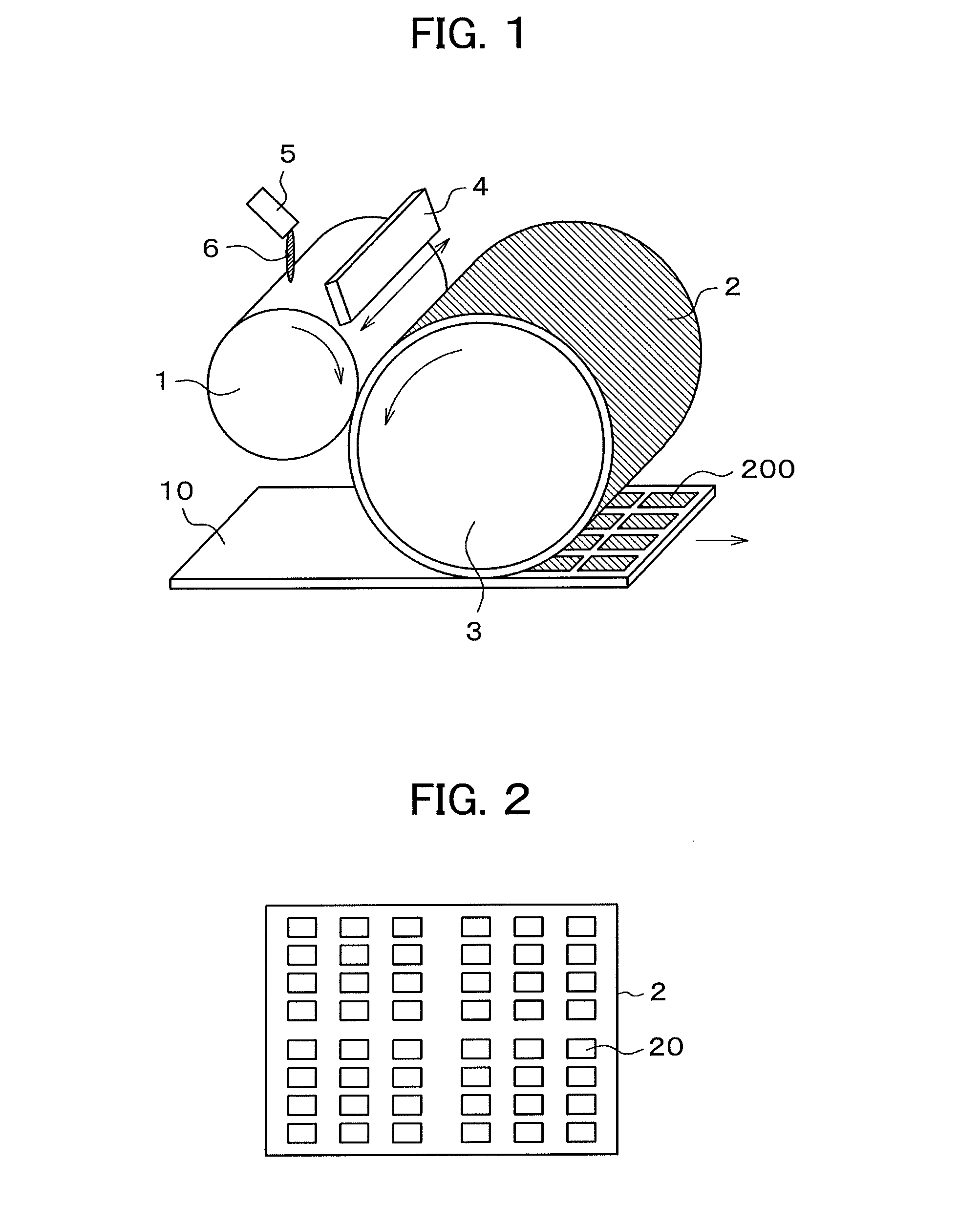
[0033]FIG. 1 is a schematic diagram illustrating an example of a configuration of a flexographic printing system for an oriented film. In FIG. 1, an oriented film material 6 is dipped onto an anilox roll 1 through an injection nozzle 5. The injection nozzle 5 is scanned in an axial direction of the anilox roll 1 so as to uniformly apply the oriented film material 6 onto the anilox roll 1. As the anilox roll 1 rotates, a doctor blade 4 is swung in directions of arrows so as to more uniformly apply the oriented film material 6 onto the anilox roll 1.

[0034]The oriented film material 6 which has been applied onto the anilox roll 1 is transferred to a printing plate 2 wound on a plate cylinder 3 and then is transferred to a mother substrate 10, thereby printing an oriented film 200 onto the mother substrate 10. The printing plate 2 transfers the oriented film to the mother substrate 10 which is traveling in a direction of an arrow while rotating in a direction of an arrow.

[0035]Here, the...

embodiment 2

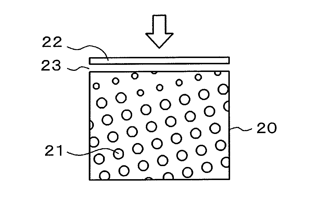
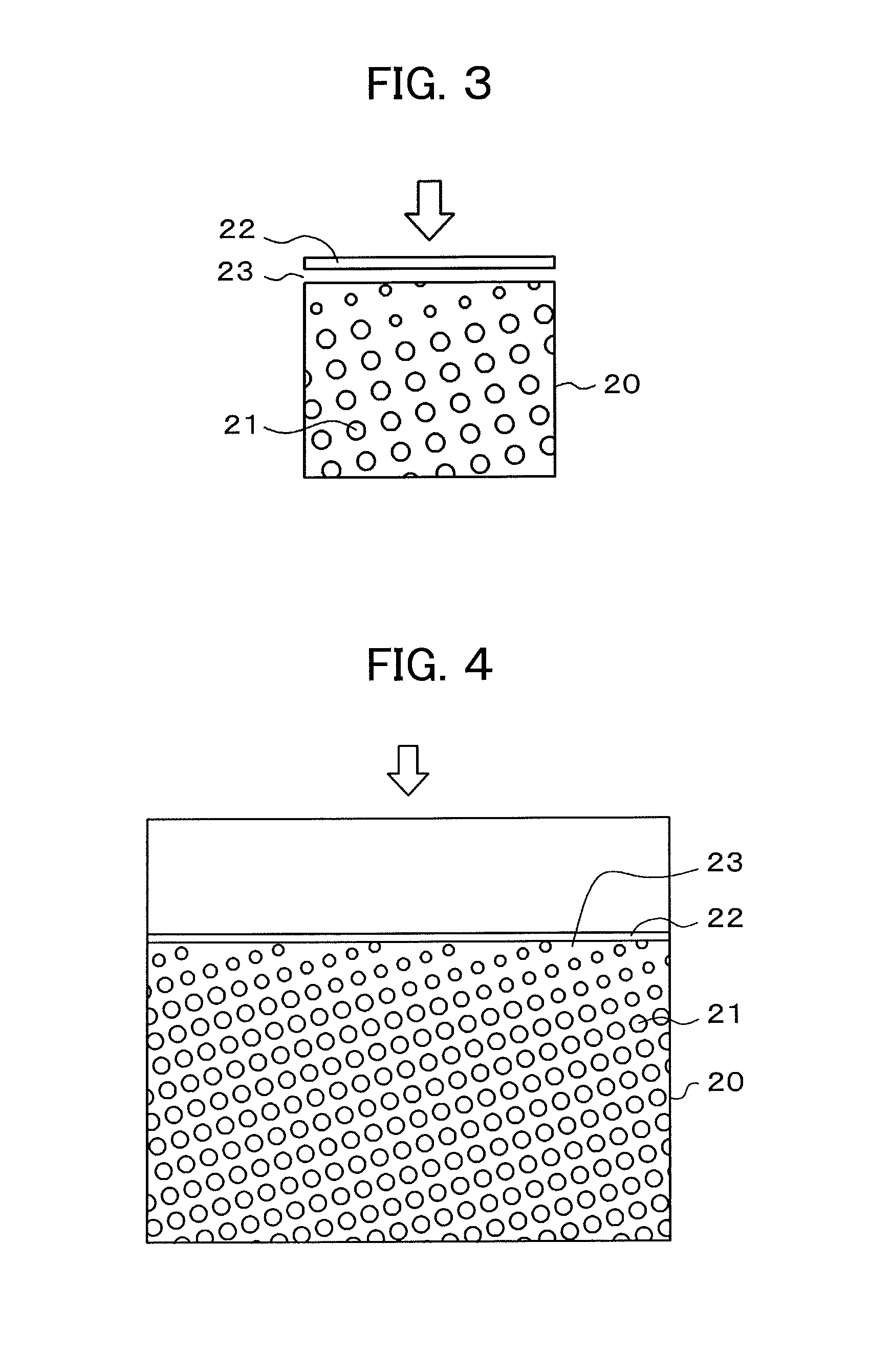
[0049]In Embodiment 1, a case that wiping of the oriented film print pattern 20 is performed only from one direction as illustrated in FIG. 3 has been described. However, in an actual device, in some cases it is desirable to configure so as to perform wiping of the oriented film print pattern 20 from any direction. FIG. 7 illustrates an example of the oriented film print pattern 20 coping with the above-mentioned case. In FIG. 7, the linear bank 22 is formed so as to surround the oriented film print pattern 20 including the protruded parts 21. The space 23 is formed between the bank 22 and the protruded parts 21. Although the space 23 is exaggeratedly illustrated in FIG. 7, it is allowable that a space of an extent that the protruded parts 21 are not formed contiguously to the bank 22 is left in reality.

[0050]In FIG. 7, the diameters of the protruded parts 21 are made larger in the region in the vicinity of the center and smaller in the peripheral region. A way of changing the diame...


PUM

PropertyMeasurementUnit
diameteraaaaaaaaaa
diameteraaaaaaaaaa
width d3aaaaaaaaaa

Abstract

In order to prevent protruded parts formed on an oriented film print pattern of a printing plate for flexographic printing from being lost, a linear bank is formed on the periphery of one side of the oriented film print pattern where wiping work is started. The bank prevents the protruded part in the oriented film print pattern from being lost by the wiping work. The protruded parts are formed in a matrix in order to retain an oriented film liquid in the oriented film print pattern. Thickness irregularity of the oriented film due to presence of the bank is reduced by making the diameters of the protruded parts smaller in a peripheral region than in a central region of the oriented film print pattern and forming a space between the peripheral-side protruded parts and the bank.

Description

CLAIM OF PRIORITY[0001]The present application claims priority from Japanese Patent Application JP 2012-276435 filed on Dec. 19, 2012, the content of which is hereby incorporated by reference into this application.BACKGROUND OF THE INVENTION[0002]1. Field of the Invention[0003]The present invention pertains to a display device and more particularly relates to a liquid crystal display device manufacturing method for forming an oriented film by flexographic printing and allowing an increase of the yield of liquid crystal display devices, and a printing plate used in the flexographic printing.[0004]2. Description of the Related Art[0005]On a liquid crystal display panel used in a liquid crystal display device, a TFT substrate and a counter substrate are arranged. On the TFT substrate, pixels including pixel electrodes, thin film transistors (TFTs) and so forth are formed in a matrix. The counter substrate faces the TFT substrate and has color filters and so forth formed at locations co...

Claims


Application Information

Patent Timeline
Patent Type & Authority Applications(United States)
IPC IPC(8): B41N1/12G02F1/1337G02F1/1333
CPCG02F1/13378B41C1/003B41C1/006B41C1/05B41M1/04B41M1/26B41N1/12G02F1/1337G02F1/133707G02F1/133711G02F1/133784
Inventor YUGE, SHUNSUKEMIYAIRI, HIROSHI
Owner JAPAN DISPLAY INC
Why Eureka
Try Eureka