

Boosted Differential Class H Amplifier
- Summary
- Abstract
- Description
- Claims
- Application Information
AI Technical Summary
Benefits of technology
Problems solved by technology
Method used
Image

Examples
Embodiment Construction
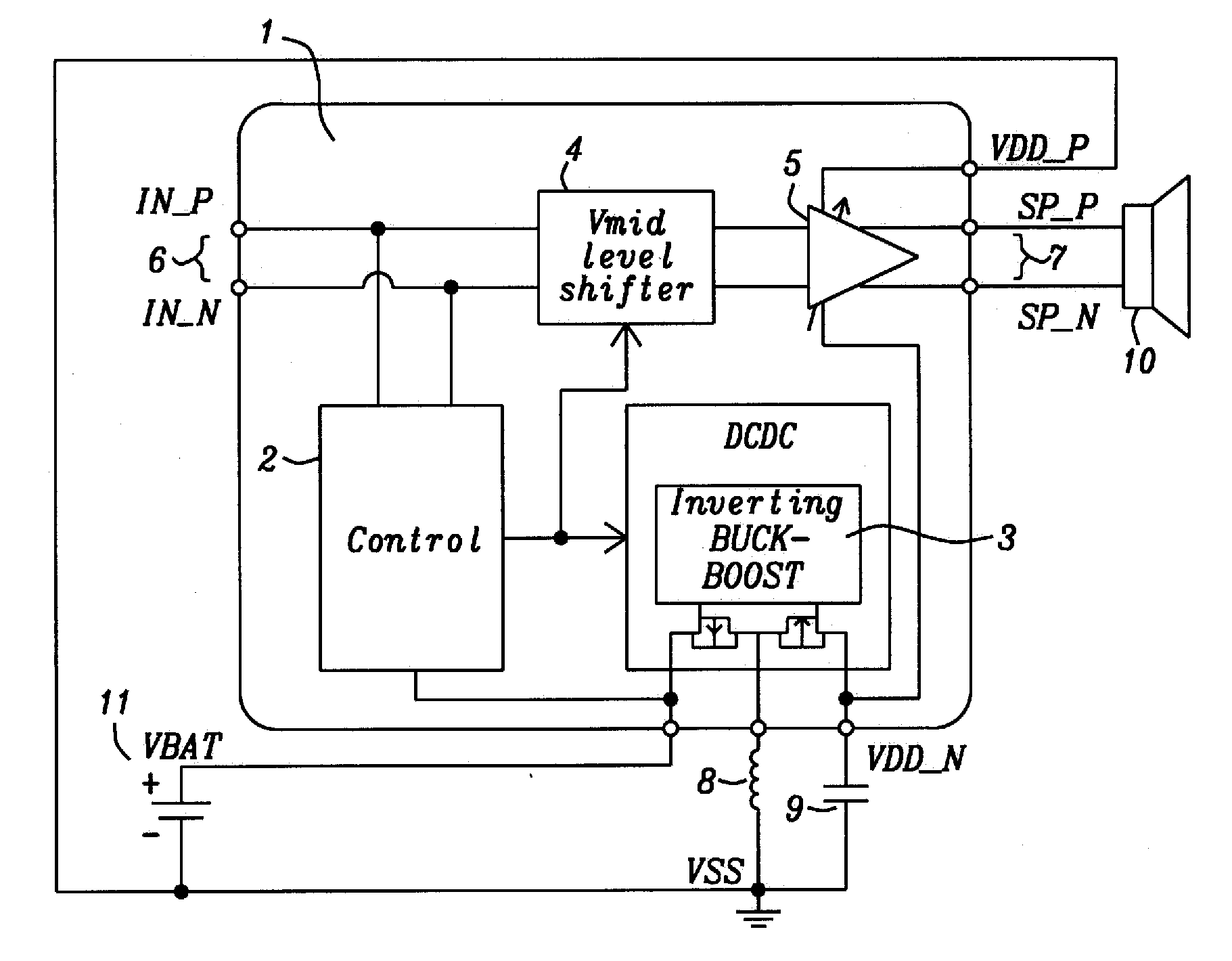
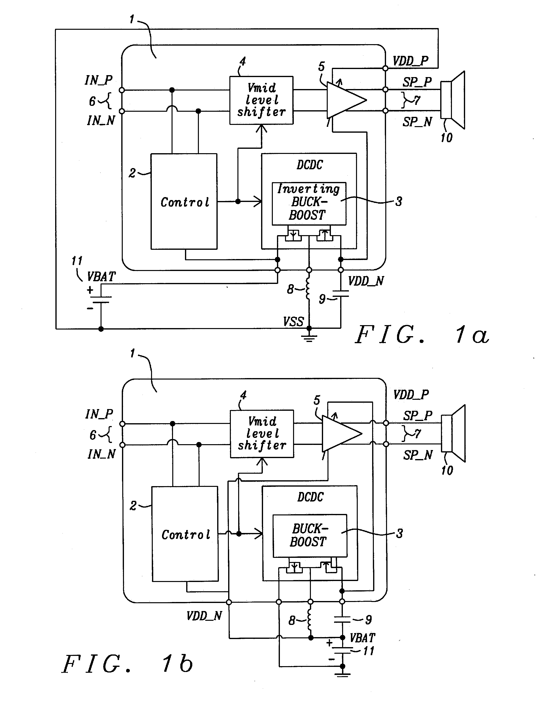
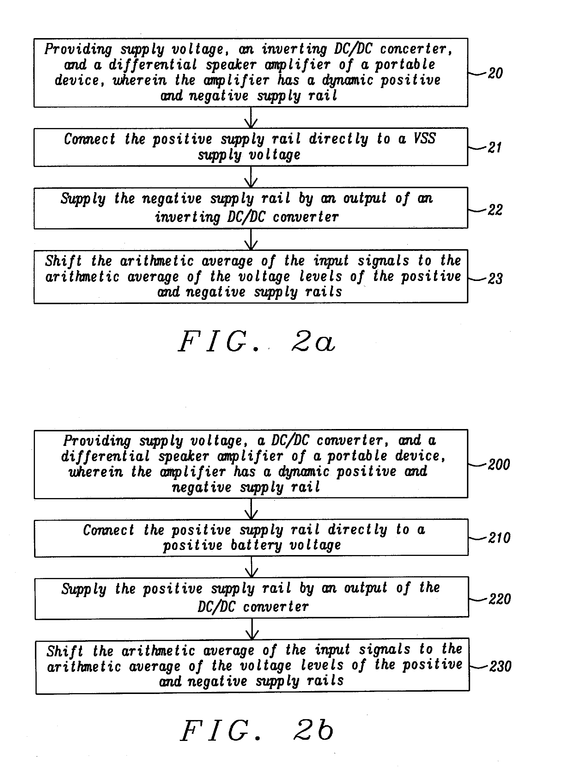
[0031]Methods and apparatus to achieve a boosted differential amplifier with inverted supply voltage are disclosed. The amplifier invented is preferably applied as audio amplifier for mobile electronic devices.
[0032]The amplifier disclosed has been designed to achieve also high power efficiency. The power efficiency is measured by the total battery playtime. This can be derived from the time averaged power consumption of the amplifier.
[0033]A differential output stage has been selected for the amplifier disclosed so that DC-offset at the positive and negative output ports subtracts to zero at the connected speaker input. Also it has been defined that the mini-speaker output power should not be further increased by reducing the electrical impedance of the speaker. The full-scale signal is defined by the supply voltage (battery voltage) and by that the maximum electrical output power. It is assumed that the achievable loudness for a typical (portable) application using a small 8 O min...
PUM
 Abstract
Description
Claims
Application Information