
Compressor motor housing and method of manufacturing

Inactive Publication Date: 2014-06-19
HAMILTON SUNDSTRAND CORP
View PDF4 Cites 0 Cited by
  • Summary
  • Abstract
  • Description
  • Claims
  • Application Information

AI Technical Summary

Benefits of technology

The invention is a compressor motor housing with an O-ring groove and an O-ring seal. The O-ring groove is formed in the aft region of the housing and has a specific width ratio and depth. The O-ring seal simultaneously contacts the axially forward and aft faces and the circumferential face of the housing. The technical effect of this design is to improve the sealing performance and efficiency of the compressor motor housing.

Problems solved by technology

However, some applications require both high pressure conditions and vacuum operation proximate one side of the seal.
During such a condition, dirt, contaminants, and foreign objects may fall into the void, which unfortunately cause damage to the seal when reenergized at high pressure.
Such damage may result in leakage of oil, refrigerant and air, among other undesirable effects.

Method used


Image

  • Compressor motor housing and method of manufacturing
  • Compressor motor housing and method of manufacturing
  • Compressor motor housing and method of manufacturing

Examples


Embodiment Construction

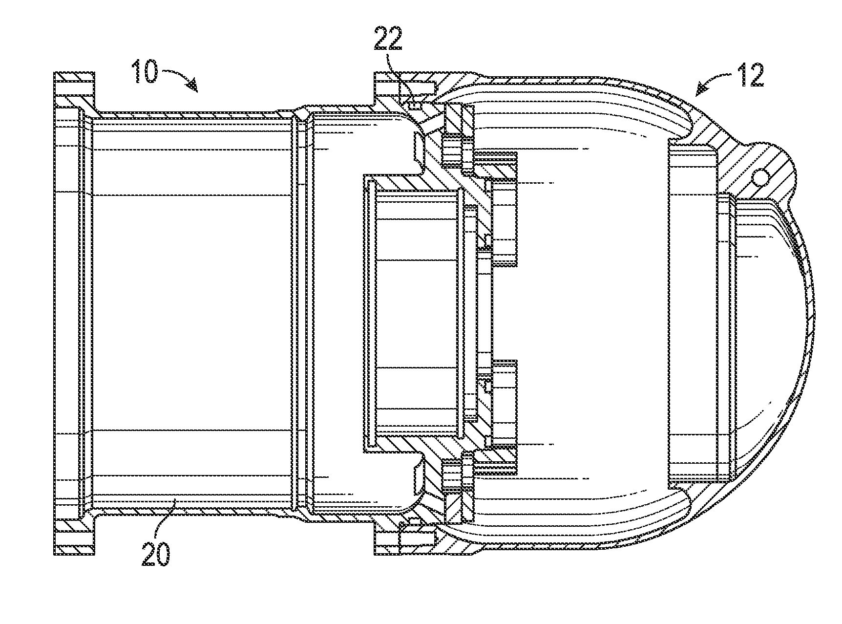
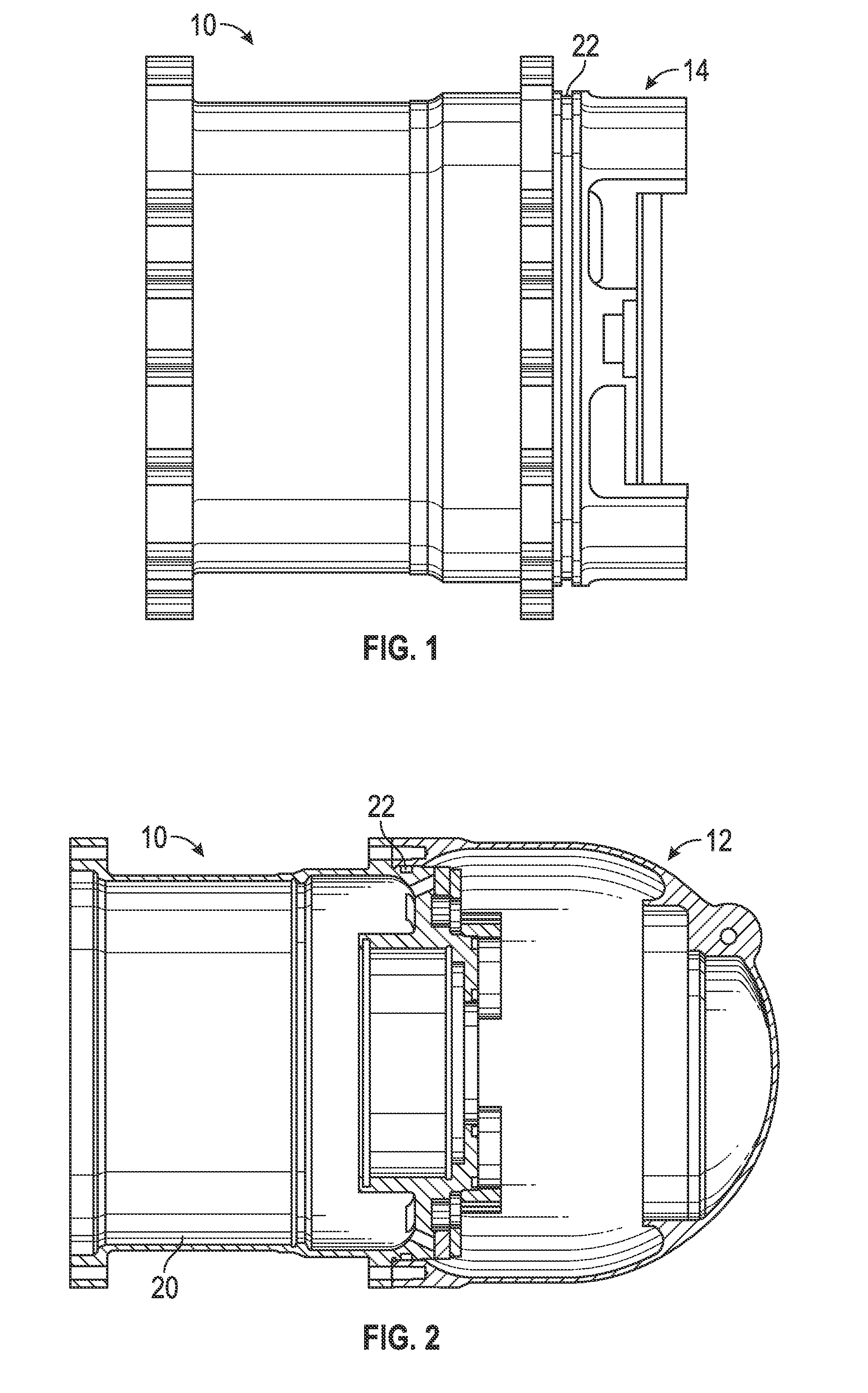
[0012]Referring to FIG. 1, a compressor motor housing 10 is generally illustrated. The compressor motor housing 10 provides a structural enclosure for a variety of components to be employed in conjunction with an application of use, such as a motor (not illustrated). The particular application may vary widely, with one exemplary embodiment related to a cooling system, such as a primary or supplemental cooling unit and / or cargo refrigeration unit disposed on an aircraft. As noted above, the compressor motor housing 10 may be used in numerous applications and the embodiments listed above are merely illustrative and not limiting.

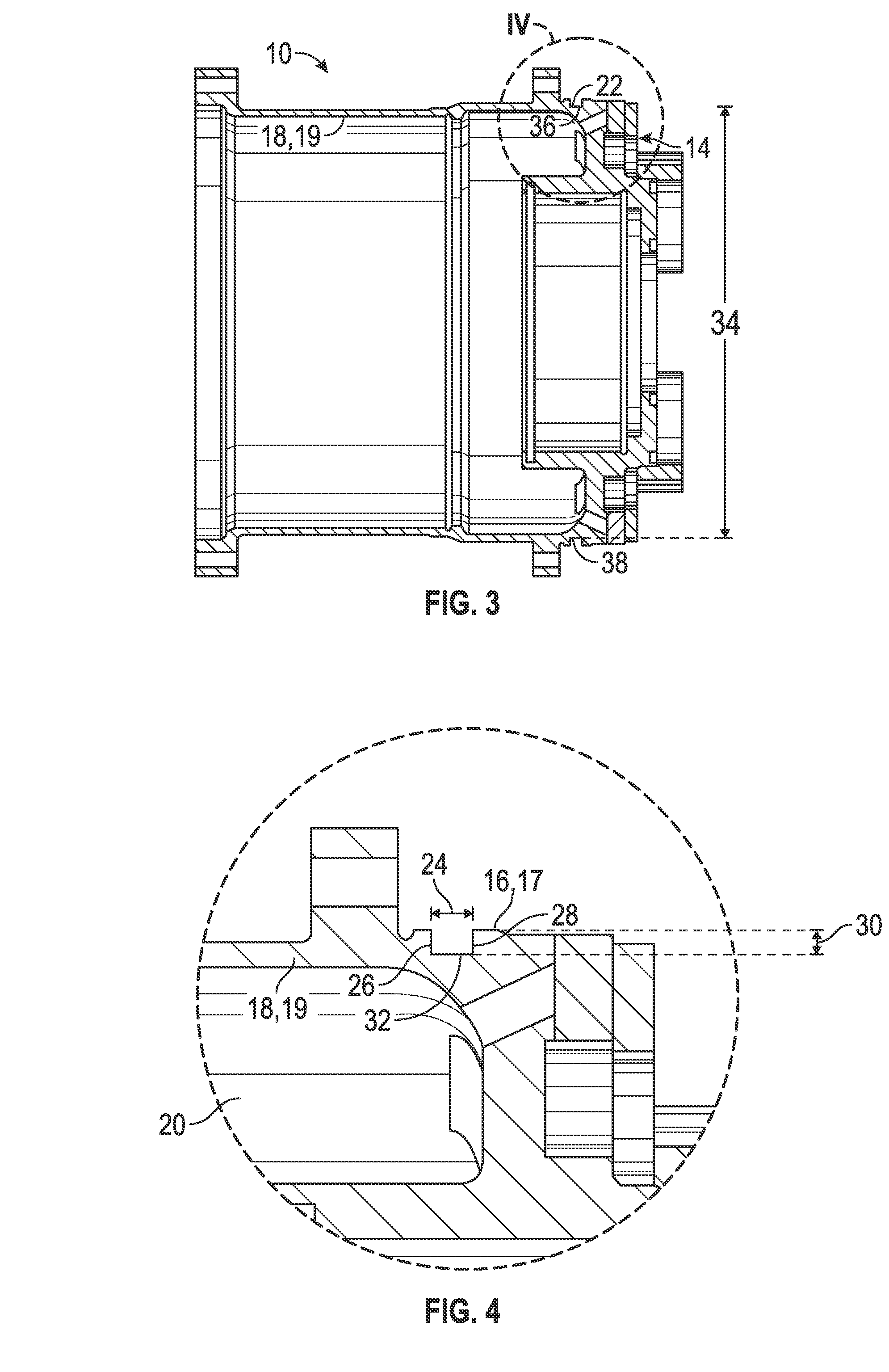
[0013]Referring now to FIGS. 2-4, in conjunction with FIG. 1, the compressor motor housing 10 includes an aft region 14 that is fixable to an end cap 12. The compressor motor housing 10 includes a radially outer surface 16 defining an outer diameter 17 and a radially inner surface 18 defining an inner diameter 19 enclosing a portion of an inner chamber 20. The ...


PUM

PropertyMeasurementUnit
Lengthaaaaaaaaaa
Lengthaaaaaaaaaa
Lengthaaaaaaaaaa

Abstract

A compressor motor housing includes an aft region having a radially inner surface defining an inner diameter and a radially outer surface defining an outer diameter. Also included is an O-ring groove extending around at least a portion of the aft region within the radially outer surface, the O-ring groove. The O-ring groove includes a groove width, a groove depth and a groove diameter, wherein a width ratio defined by the groove width in relation to the groove diameter ranges from about 0.0257 to about 0.0272. The O-ring groove also includes an axially forward face, an axially aft face and a circumferential face disposed radially outwardly from the radially inner surface. The compressor motor housing further includes an O-ring seal simultaneously disposed in contact with the axially forward face, the axially aft face and the circumferential face.

Description

BACKGROUND OF THE INVENTION[0001]The present invention relates to cooling systems, and more particularly to compressor motor housings for such cooling systems, as well as a method of manufacturing a compressor motor housing.[0002]O-ring seal arrangements are employed in a wide variety of applications for sealing purposes. Typically, the O-ring seal is seated within an O-ring groove and compressed to cause a reactive force which seals a passage between two surfaces and regions. As pressure is applied to compress the seal, the seal often displaces against a wall of the O-ring groove, thereby distorting the seal further and providing an increased reactive force on the two surfaces to be sealed. Such an arrangement is suitable when high pressure is consistently applied on one side of the seal since the seal is moved against the same wall of the O-ring groove. However, some applications require both high pressure conditions and vacuum operation proximate one side of the seal. Under vacuu...

Claims


Application Information

Patent Timeline
IPC IPC(8): F01D25/24B23P13/00
CPCF16J15/062Y10T29/49995
Inventor RUPP, CAROLINEBEERS, CRAIG MATTHEWITALIA, LINO SEBASTIANO
Owner HAMILTON SUNDSTRAND CORP
Learn More