Method for ultrasonic fatigue testing at high temperature, and testing device

a testing device and ultrasonic technology, applied in the direction of fluid tightness measurement, instruments, structural/machine measurement, etc., can solve the problems of many problems to be solved

Inactive Publication Date: 2014-06-26
NAT INST FOR MATERIALS SCI
View PDF14 Cites 6 Cited by
  • Summary
  • Abstract
  • Description
  • Claims
  • Application Information

AI Technical Summary

Benefits of technology

[0042]According to the invention, fatigue properties at high temperature which could be evaluated only about 107 cycles in the related art can be evaluated up to a gigacycle region beyond 109 cycles.
[0043]In the related art, since a fatigue test could be performed only at low speed of about 10 to 100 Hz, when evaluating fatigue due to fast vibration in a turbine blade or the like, it was necessary to neglect the effect of a frequency. In contrast, according to the invention, since a fatigue test can be performed at high speed close to actual equipment, the effect of the frequency can also be appropriately evaluated.

Problems solved by technology

However, since this method is special, in realizing a test at high temperature, there are many problems to be solved.

Method used


Image

  • Method for ultrasonic fatigue testing at high temperature, and testing device
  • Method for ultrasonic fatigue testing at high temperature, and testing device
  • Method for ultrasonic fatigue testing at high temperature, and testing device

Examples


example 1

[0100]Temperature dependency of Young's modulus was linearly approximated. Convergent calculation was performed using Young's modulus measured at room temperature and the L2 value measured at the test temperature, and temperature dependency of Young's modulus was obtained. Numerical calculation was performed using the Runge-Kutta's formula.

[0101]FIG. 6 shows a display screen of produced stress calculation software. This inverse calculation function of Young's modulus is incorporated.

[0102]FIG. 7 shows the result of comparison between obtained Young's modulus and a literature value of Young's modulus of a material similar in component, microstructure, and strength.

[0103]Although (a) shows the results obtained for 12Cr-2W steel, this tends to well match the literature value reported for ASME T91 steel.

[0104]Although the result of this example tends to be higher at near 600° C., this is considered because, while 2% of tungsten (W) is added to the material measured in this example, and ...

example 2

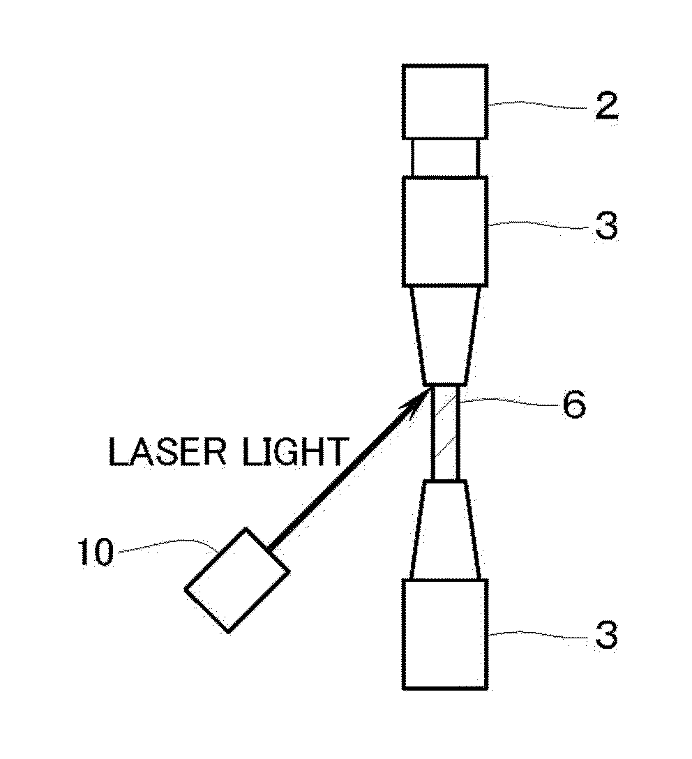
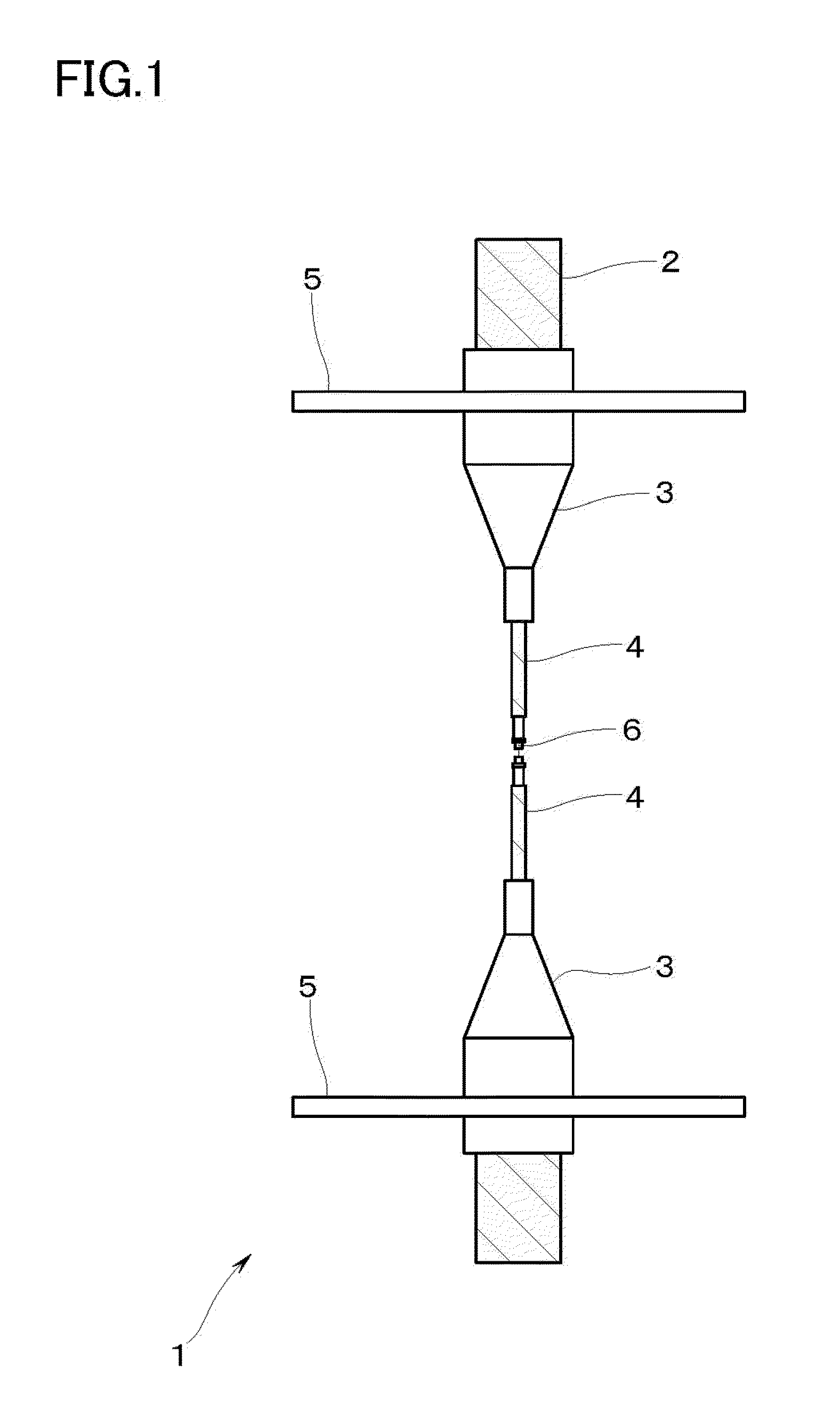
[0107]The device of the invention shown in FIG. 1 having the rods and the horns attached to both ends of the test specimen was used.

[0108]A mode of a temperature distribution measurement in the configuration in which the rods and the horns are attached to both ends of the test specimen is shown in FIG. 8, and a measurement result is shown in Table 1.

[0109]Although Nos. 5 and 7 of FIG. 8 correspond to the temperature at the leading end of the rod, since both are substantially matched in temperature, it can be confirmed that the temperature distribution is symmetrical in the vertical direction.

[0110]Although the temperature at a position closest to the vibrator corresponds to No. 10, since the temperature of No. 10 is substantially about 30° C. even if heating at about 1000° C. is performed, it can be confirmed that sufficient heat insulation is obtained in the device configuration of this example.

[0111]The temperature distribution reaches a stationary state by heating for about two h...

example 3

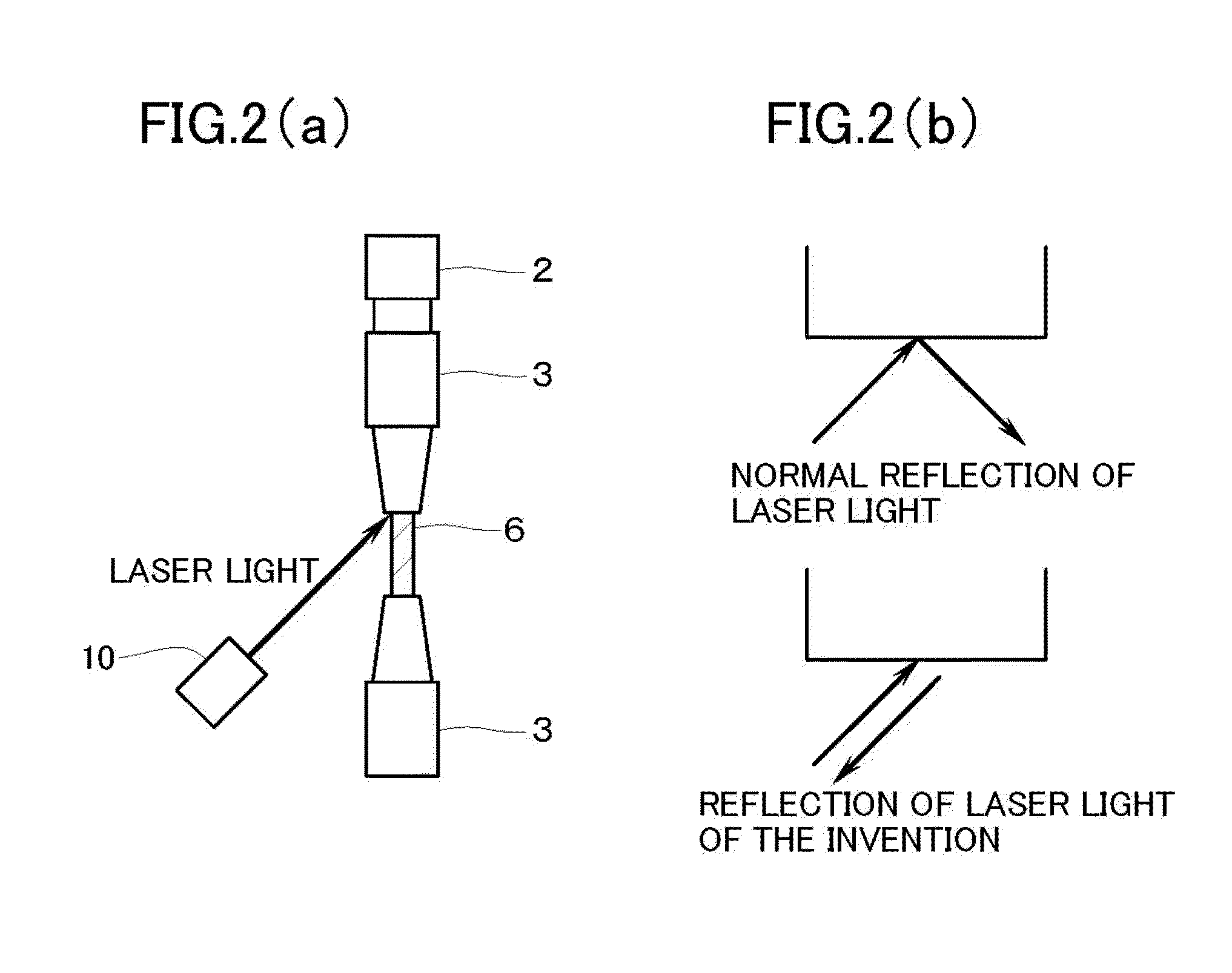
[0113]FIG. 9 shows the result of comparison between end surface displacement measured by the configuration of FIGS. 1 to 3 and end surface displacement measured using a normal free end.

[0114]Here, laser light was irradiated from a direction of 35° with respect to the horizontal direction, and a chamfered part (FIG. 3(d)) of 35° was provided in the horn (in this case, the rod) so as to be perpendicular with respect to the horn.

[0115]As will be apparent from FIG. 9, the measurement result of the invention well matches the measurement result by the normal method. That is, validity of the end surface displacement measurement of the invention was confirmed.


PUM

PropertyMeasurementUnit
heat resistanceaaaaaaaaaa
temperatureaaaaaaaaaa
diameteraaaaaaaaaa

Abstract

Disclosed are a method for ultrasonic fatigue testing at high temperature and a testing device without needing preliminary Young's modulus measurement, and a method for ultrasonic fatigue testing at high temperature and a testing device capable of securing heat insulation for protecting a vibrator without water cooling of a horn, measuring end surface displacement of a test specimen in a noncontact manner, and solving problems of a noncontact temperature measurement of a test specimen and temperature control. Young's modulus is calculated by inverse calculation, a rod and a horn having heat resistance, heat insulation, and temperature symmetry of a test specimen are used, laser light is irradiated and received from an oblique direction to measure end surface displacement, and a noncontact temperature measurement of a test specimen by a black-body coating and a two-color radiation thermometer and temperature control by a high-frequency coil having a special shape are performed.

Description

TECHNICAL FIELD[0001]The present invention relates to a method for ultrasonic fatigue testing at high temperature, and a testing device. In particular, the present invention relates to a method and device for carrying out an ultrasonic fatigue test with high precision by a new advanced technology of control of stress amplitude to be applied to a test specimen and temperature control of the test specimen at high temperature.BACKGROUND ART[0002]An ultrasonic fatigue test is a fatigue testing method which uses resonance with free vibration of a test specimen (NPL 1).[0003]The ultrasonic fatigue test is a powerful tool which can realize an ultrafast fatigue test at 20 kHz 200 cycles higher than the normal, and performs a gigacycle fatigue test 109 cycles or more.[0004]In a turbine blade, such as a gas turbine, it is known that kHz order vibration occurs during operation. In simulating fatigue due to fast vibration, it can be said that the ultrasonic fatigue test is an optimum testing me...

Claims


Application Information

Patent Timeline
Patent Type & Authority Applications(United States)
IPC IPC(8): G01N3/32G01N29/22
CPCG01N3/32G01N2203/0005G01N2203/0008G01N2203/0226G01N2291/02827G01N29/12G01N29/228G01N29/2418G01N2291/0258G01N2203/0658
Inventor FURUYA, YOSHIYUKI
Owner NAT INST FOR MATERIALS SCI
Why Eureka
Try Eureka