
Fuel injection valve

a fuel injection valve and valve body technology, applied in the direction of fluid pressure injection control, fuel injection apparatus, charge feed system, etc., can solve the problems of increasing the response delay, and increasing so as to reduce the pressure in the control chamber, shorten the fuel injection interval among multiple injections, and smoothly carry out the next fuel injection

Active Publication Date: 2014-06-26
DENSO CORP
View PDF2 Cites 9 Cited by
  • Summary
  • Abstract
  • Description
  • Claims
  • Application Information

AI Technical Summary

Benefits of technology

The patent text describes a method to decrease the pressure in a control chamber before a movable plate makes contact with a fixed plate. This is done by injecting fuel at a specific time to match the opening pressure of a valve. The decreased pressure helps to achieve a smooth fuel injection without being affected by the delay in the control chamber pressure or the time needed for the movable plate to make contact. This method also allows for a faster fuel injection interval between multiple injections.

Problems solved by technology

As a result, response for starting the fuel injection is getting worse.
Then, response for terminating the fuel injection is getting worse.
However, there exists a response delay between change of the control-chamber pressure and an actual opening or closing operation of the valve body.
Therefore, due to the response delay, there exists a limit for shortening the injection interval from a timing of the termination of the fuel injection to a timing at which the control-chamber pressure is decreased to the valve-body opening pressure by opening the control valve.

Method used


Image

  • Fuel injection valve
  • Fuel injection valve
  • Fuel injection valve

Examples


first embodiment

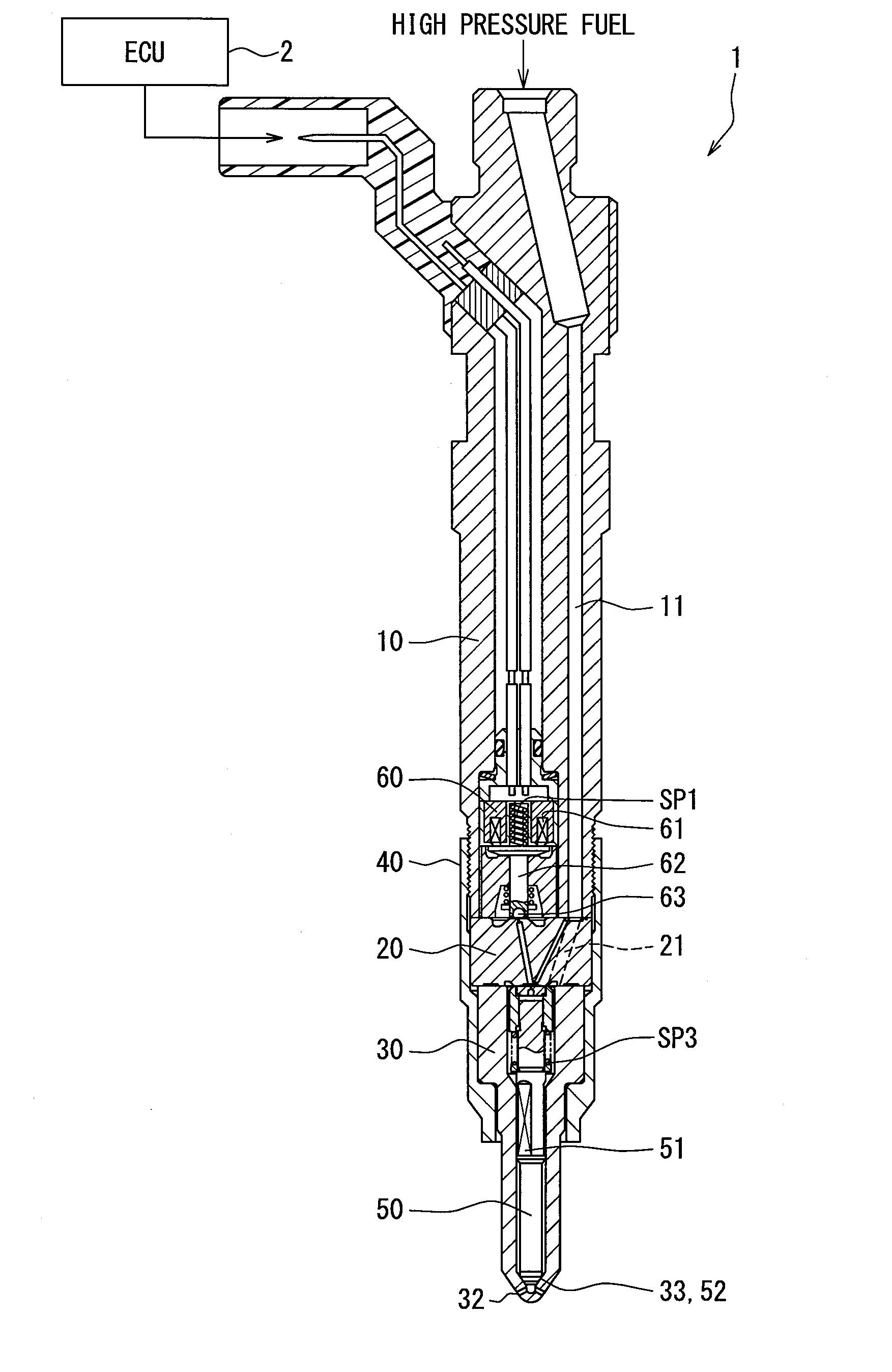
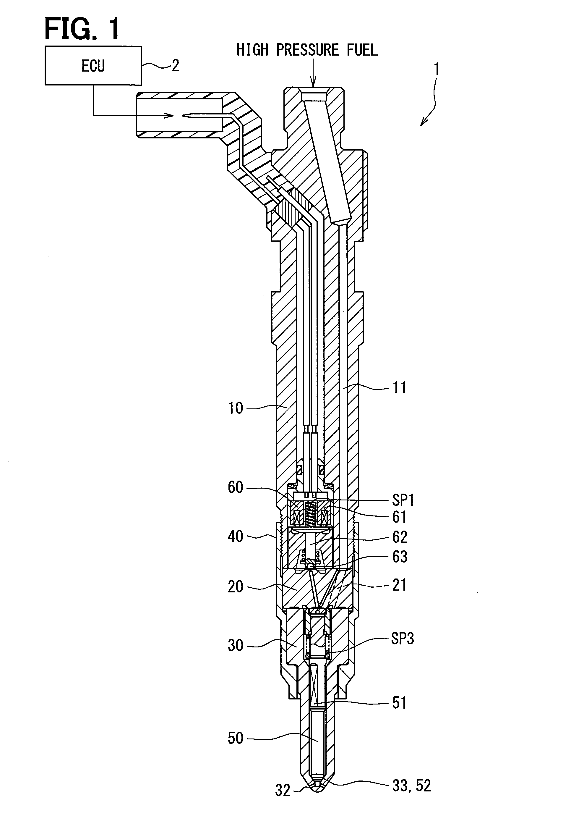
[0044]FIGS. 1 to 4 shows a fuel injection system, according to which a single injection (not multi-stage injection) is carried out.

[0045]A fuel injection valve 1 shown in FIG. 1 is operated by a drive current outputted from an electronic control unit 2 (hereinafter, the ECU 2). The ECU 2 calculates a target injection amount based on engine load “L”, engine rotational speed “NE” and so on. The ECU 2 calculates an injection time period, which corresponds to the target injection amount, depending on pressure of high-pressure fuel to be supplied to the fuel injection valve 1. The ECU 2 calculates a power-supply time period depending on the above calculated injection time period, wherein a delay time for starting fuel injection as well as a delay time for terminating the fuel injection is taken into consideration. Then, the drive current is supplied to the fuel injection valve 1 during the power-supply time period.

[0046]The fuel injection valve 1 is composed of a holder 10 made of metal,...

second embodiment

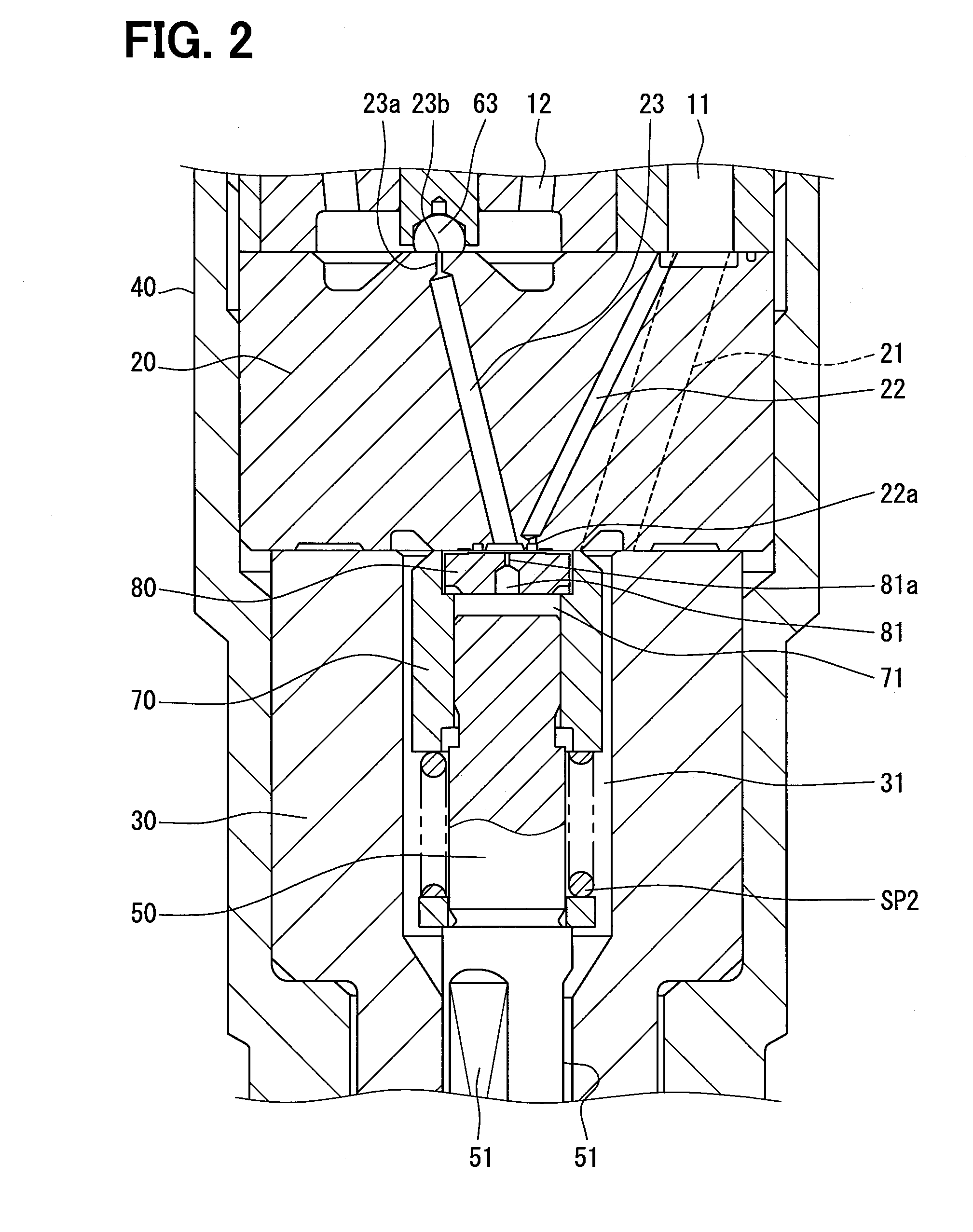
[0121]In the first embodiment, as shown in FIG. 2, the sub out-orifice 23a is formed at a most downstream side of the low pressure passage 23. Namely, the sub out-orifice 23a is opened or closed by the control valve 63.

[0122]According to the present embodiment, as shown in FIG. 11, a cross sectional area of an outlet port 23d of the low pressure passage 23 is made larger than that of the sub out-orifice 23a. Accordingly, the outlet port 23d, which is formed at the downstream side of the sub out-orifice 23a, is opened or closed by the control valve 63.

[0123]In the first embodiment of FIG. 2, the flow rate (the fuel discharging amount) restricted by the sub out-orifice 23a varies when a distance between the control valve 63 in the opened condition and the sub out-orifice 23a is changed. It is not possible to exactly measure the flow rate of the sub out-orifice 23a by experiments using the fixed plate 20 by itself. It is only possible to measure the flow rate in the experiments using t...

third embodiment

[0125]In the first embodiment, the orifice diameters of the sub out-orifice 23a and the in-orifice 22a are so set that the control-chamber pressure “Pcon” (the steady pressure) in the steady-state situation coincides with the valve-body opening pressure “PO”. According to the third embodiment, however, the orifice diameters of the sub out-orifice 23a and the in-orifice 22a are so set that a difference between the steady pressure and the valve-body opening pressure “PO” is within a predetermined range.

[0126]More exactly, the value of “Qin / Qsub” is set to be within a range of plus or minus 30% of the ratio “Qin / Qsub” calculated based on the formulas 4 and 7.

[0127]Orifice diameters of the out-orifice 81a and the sub out-orifice 23a are so set that the flow rate “Qout” of the out-orifice 81a is made smaller than the flow rate “Qsub” of the sub out-orifice 23a. More preferably, the orifice diameters of the out-orifice 81a and the sub out-orifice 23a are so set that the flow rate “Qout” o...


PUM


Abstract

A sub out-orifice and an in-orifice are respectively formed in a low pressure passage and a high pressure passage of a fixed plate. A control valve is provided at an outlet port of the low pressure passage. In a normal control, the control valve starts its control-valve opening operation when a movable plate is in contact with the fixed plate. In an interval-shortening control, the control valve starts the control-valve opening operation at an earlier timing than that in the normal control, namely during a course in which a valve body is still in its valve-body closing operation.

Description

CROSS REFERENCE TO RELATED APPLICATION[0001]This application is based on Japanese Patent Application No. 2012-283498 filed on Dec. 26, 2012 the disclosure of which is incorporated herein by reference.FIELD OF TECHNOLOGY[0002]The present disclosure relates to a fuel injection valve used in a fuel injection system for injecting fuel into an internal combustion engine.BACKGROUND[0003]A fuel injection valve of this kind generally has such a structure, according to which fuel pressure in a pressure control chamber (control-chamber pressure) is controlled so as to operate a valve body, which opens or closes an injection port for injecting fuel. Namely, the control-chamber pressure biases the valve body in a valve-body closing direction. The valve body is moved in a valve-body opening direction when the control-chamber pressure is decreased, while the valve body is moved in the valve-body closing direction when the control-chamber pressure is increased.[0004]The fuel injection valve of thi...

Claims


Application Information

Patent Timeline
Patent Type & Authority Applications(United States)
IPC IPC(8): F02M51/06
CPCF02M63/0007F02M47/027F02M55/008F02M61/12F02M2547/001F02M63/0054
Inventor ADACHI, NAOFUMI
Owner DENSO CORP
Learn More