Aircraft front portion having an improved landing gear bay

a technology for landing gear and aircraft, which is applied in the field of aircraft front portions, can solve the problems of difficult fitting, inconvenient working in these lateral spaces, and inconvenient installation of equipment in two lateral spaces

Inactive Publication Date: 2014-06-26
AIRBUS OPERATIONS (SAS)
View PDF11 Cites 18 Cited by
  • Summary
  • Abstract
  • Description
  • Claims
  • Application Information

AI Technical Summary

Benefits of technology

[0016]Thus, the cockpit floor performs the function of a plane for walking on but no longer participates, as in the prior art, in performing the function of taking up forces from the fuselage frames. In the prior art, this function is performed by the structural portion of the floor that includes cross-members each extending transversely between two opposite points of a given fuselage frame. That function is now incorporated directly in the landing gear storage bay, which is itself directly connected to the fuselage frames. In the absence of a structural floor portion, this makes it possible to maintain the general shape of the fuselage under the effect of pressurization. Furthermore, this direct mechanical connection between the landing gear bay and the fuselage frames provides the landing gear bay with greater ability to withstand deformation.
[0037]mechanical connection elements (e.g., rods) that are fastened to said top portion and that serve to provide mechanical connection between the landing gear storage bay and fuselage frames of the aircraft so as to take up all of the mechanical forces exerted on said fuselage frames under the effect of pressurization. Such a bay thus makes it possible to omit the structural portion of the cockpit floor that used to perform this function of taking up mechanical force via the reinforcing cross-members, thus making it possible to restrict the functions of the floor merely to providing a plane for the crew to walk on.

Problems solved by technology

The top space is of relatively small volume that is difficult to access, thus making it difficult to fit out, in particular for passing electrical connection elements and ventilation systems elements therethrough.
Furthermore, the two lateral spaces are not suitable for incorporating all types of equipment because of their relatively small volume and more particularly because of the presence of connection rods arranged obliquely between the landing gear bay and the reinforcing frames of the fuselage.
Working in these lateral spaces is thus uncomfortable.
Furthermore, integrating systems and equipment in the front bottom zone requires a large number of electrical connection elements and of ventilation systems elements between the various components in this zone, and also with the remainder of the aircraft.
In this bottom zone, the connection elements between the systems and the pieces of equipment are difficult to put into place because of the difficult access.
This must necessarily be done on board the aircraft since it is not possible to implement a preassembly outside the aircraft.
This task is made difficult by the presence of the cockpit floor.

Method used


Image

  • Aircraft front portion having an improved landing gear bay
  • Aircraft front portion having an improved landing gear bay
  • Aircraft front portion having an improved landing gear bay

Examples


Embodiment Construction

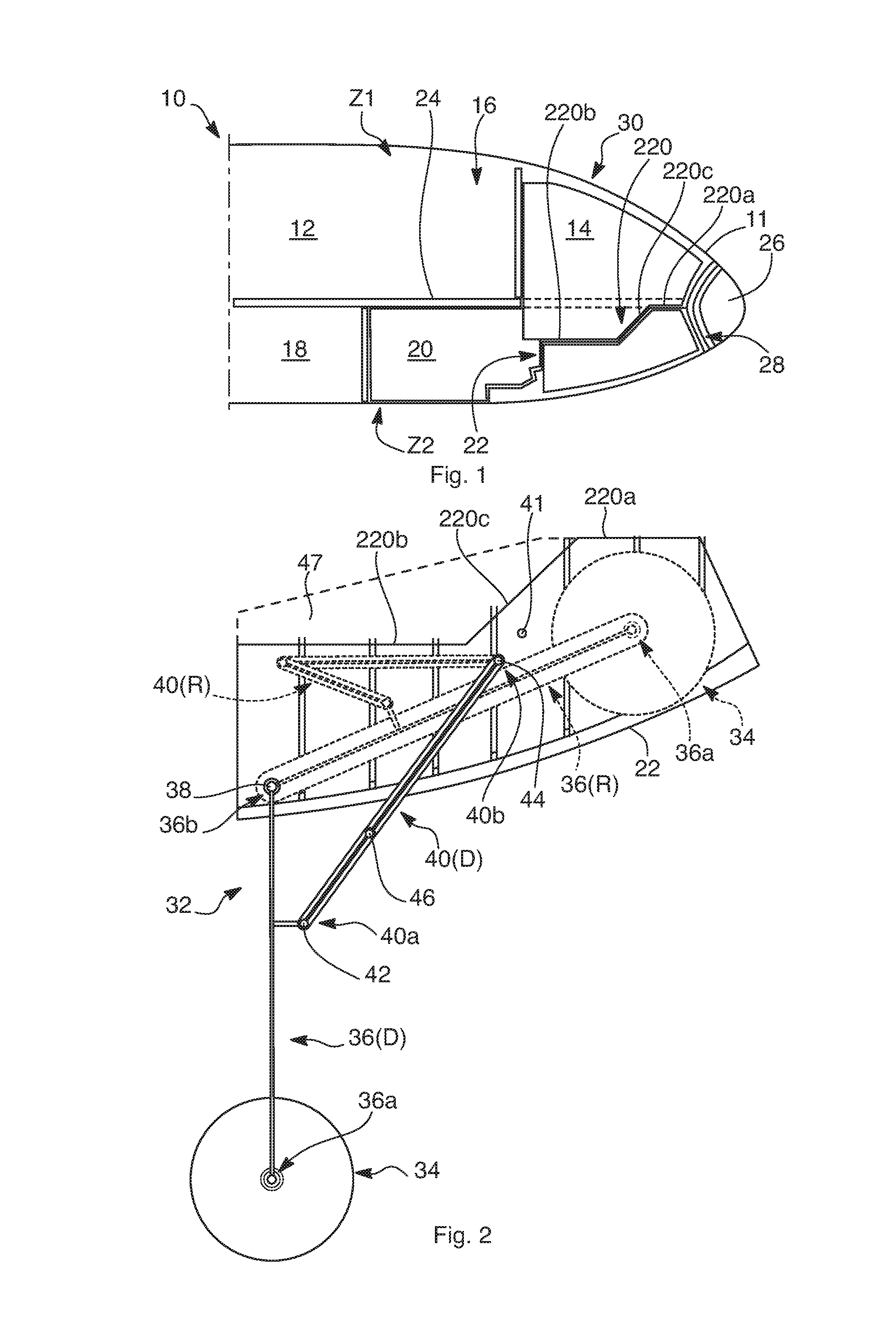
[0053]By way of example, and as shown in fragmentary longitudinal section in

[0054]FIG. 1, an aircraft given overall reference 10 includes two levels or zones, namely a top zone Z1 and a bottom zone Z2. The top zone Z1 has a cabin zone 12 dedicated to passengers and, towards the front of the aircraft, a front zone 14 dedicated to the cockpit. The front zone or cockpit 14 is separated from the cabin zone 12 by a passage 16 giving access to the cockpit. The bottom zone Z2 has a rear cargo zone 18 serving in particular to receive containers, and a front bottom zone 20 that is dedicated to integrating electronic equipment and systems (avionics bays, . . . ), and ventilation equipment and systems, and that also receives the nose landing gear housed in its landing gear bay 22. The cabin zone 12 and the access passage 16 are separated from the bottom zone Z2 by a floor 24.

[0055]At its front end, in front of the cockpit 14 and the front bottom zone 20, the aircraft has a radar equipment zone...


PUM


Abstract

An aircraft front portion in which the landing gear storage bay is arranged under a cockpit floor. The landing gear bay is mechanically connected to the fuselage frames of the aircraft front portion in order to perform the function of taking up the mechanical forces acting on the fuselage frames under the effect of pressurization. The cockpit floor is thus simplified since it serves solely as a plane for the crew to walk on and it can be lowered so as to release space in the cockpit.

Description

CROSS-REFERENCES TO RELATED APPLICATIONS[0001]This application claims the benefit of the French patent application No. 1262583 filed on Dec. 21, 2012, the entire disclosures of which are incorporated herein by way of reference.BACKGROUND OF THE INVENTION[0002]The invention relates to an aircraft front portion and to the arrangement of a nose landing gear storage bay therein.[0003]In certain aircraft, the nose landing gear storage bay is arranged in a bottom zone situated at the front of the aircraft, under the floor of the deck of the cabin zone dedicated to passengers and a front zone dedicated to the cockpit.[0004]In particular in the empty space around the nose landing gear bay, the front bottom zone also incorporates numerous electronic systems and pieces of equipment, ventilation systems, and also numerous electrical connection elements (cables, connectors, . . . ) and ventilation systems elements (pipes, couplings, ducts,[0005]More particularly, these pieces of equipment, syst...

Claims


Application Information

Patent Timeline
Patent Type & Authority Applications(United States)
IPC IPC(8): B64C25/00B64D11/00B64C1/18
CPCB64C1/068B64C25/04B64D11/00B64C1/18B64C25/001B64C1/061B64C25/14B64C1/0683
Inventor DURAND, YVESGUERING, BERNARD
Owner AIRBUS OPERATIONS (SAS)
Why Eureka
Try Eureka