
Mulitple controlled electrochromic devices for visible and ir modulation

a technology of electrochromic devices and ir modulation, which is applied in the direction of photometry using electric radiation detectors, optical radiation measurement, instruments, etc., can solve the problems of reducing aesthetics and other benefits, increasing cooling or heating costs, and requiring the removal or covering of windows to increase lighting costs

Inactive Publication Date: 2014-06-26
UNIV OF FLORIDA RES FOUNDATION INC
View PDF12 Cites 12 Cited by
  • Summary
  • Abstract
  • Description
  • Claims
  • Application Information

AI Technical Summary

Benefits of technology

The patent describes a special coating that can be applied to a surface and used to control the flow of light and heat. It allows for both manual and automatic control of the system. This technology can be useful in a variety of applications.

Problems solved by technology

Annually, about four percent of the total U.S. energy consumption results from window inefficiencies due to poor insulation and high transmission of solar radiation that allows an undesired heat gain or loss in the building that increases cooling or heating costs.
The removal or covering of windows requires an increase in costs for lighting and reduces the aesthetics and other benefits of natural light that have been demonstrated to increase a workforce's productivity and sense of well-being.
However, no system has been demonstrated that independently and simultaneously varies the heat flow (near infrared (NIR) and / or middle infrared (MIR) transmittance) and the visible transparency of the window.
While indium tin oxide (ITO) can be used as the transparent electrode(s) in dynamic windows, its inherent properties present many drawbacks for its use in flexible electrochromic devices (f-ECDs).
For example, ITO on plastic cracks and becomes unusable when repeatedly bent, making it unsuitable for retrofitting existing windows.
Furthermore, ITO reflects infrared (IR) light, and, therefore, does not permit IR transmittance at levels as high as might be desired.

Method used


Image

  • Mulitple controlled electrochromic devices for visible and ir modulation
  • Mulitple controlled electrochromic devices for visible and ir modulation
  • Mulitple controlled electrochromic devices for visible and ir modulation

Examples


Embodiment Construction

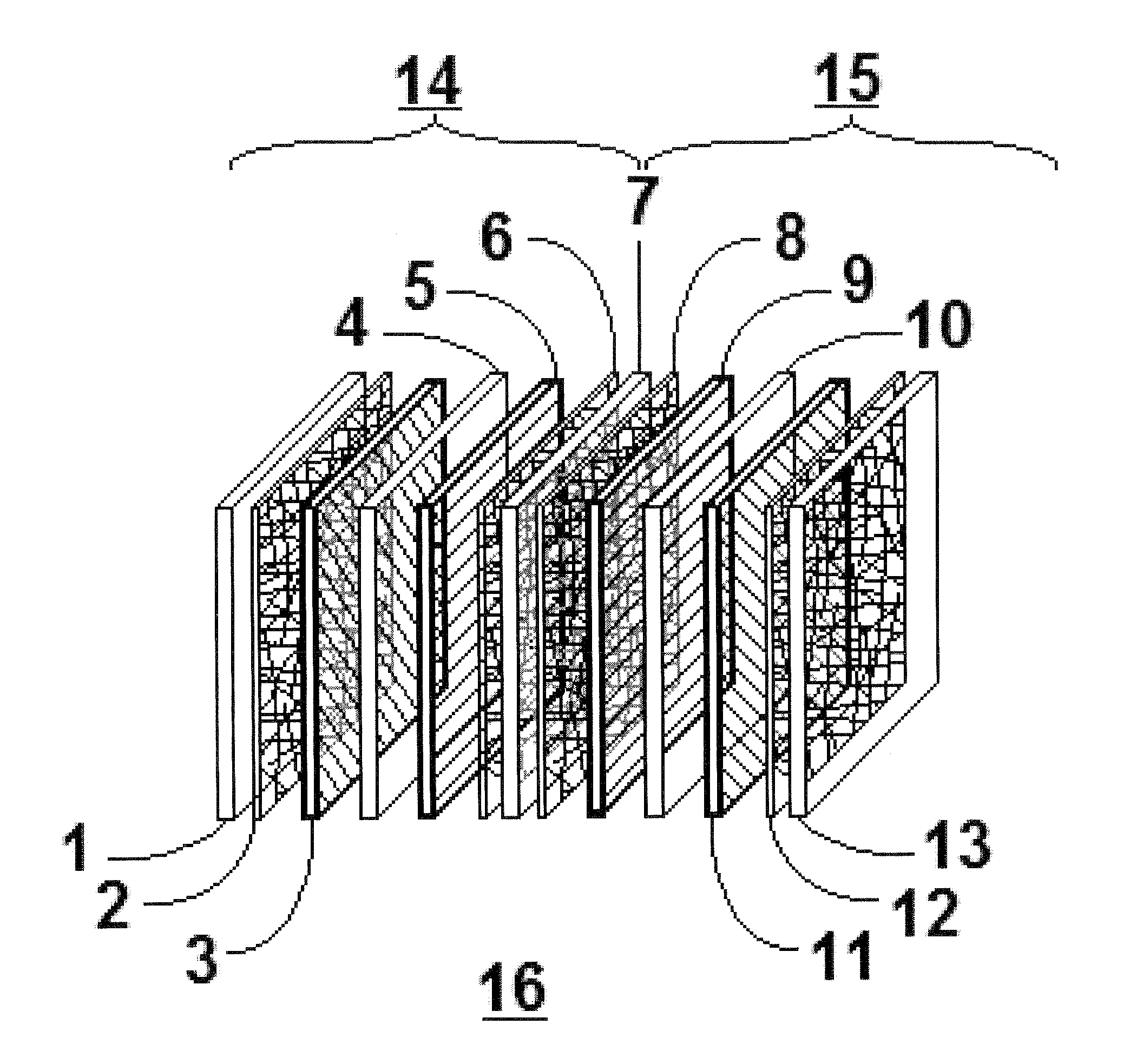
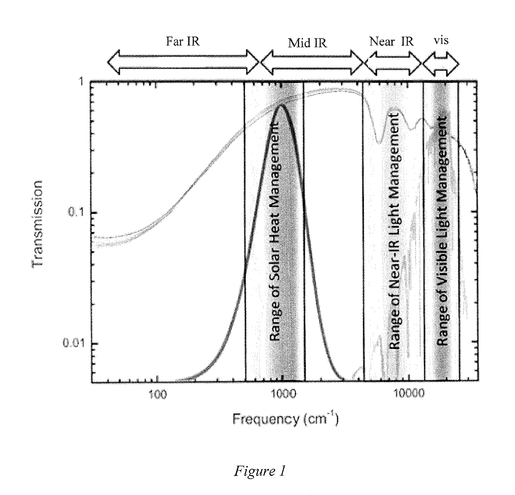
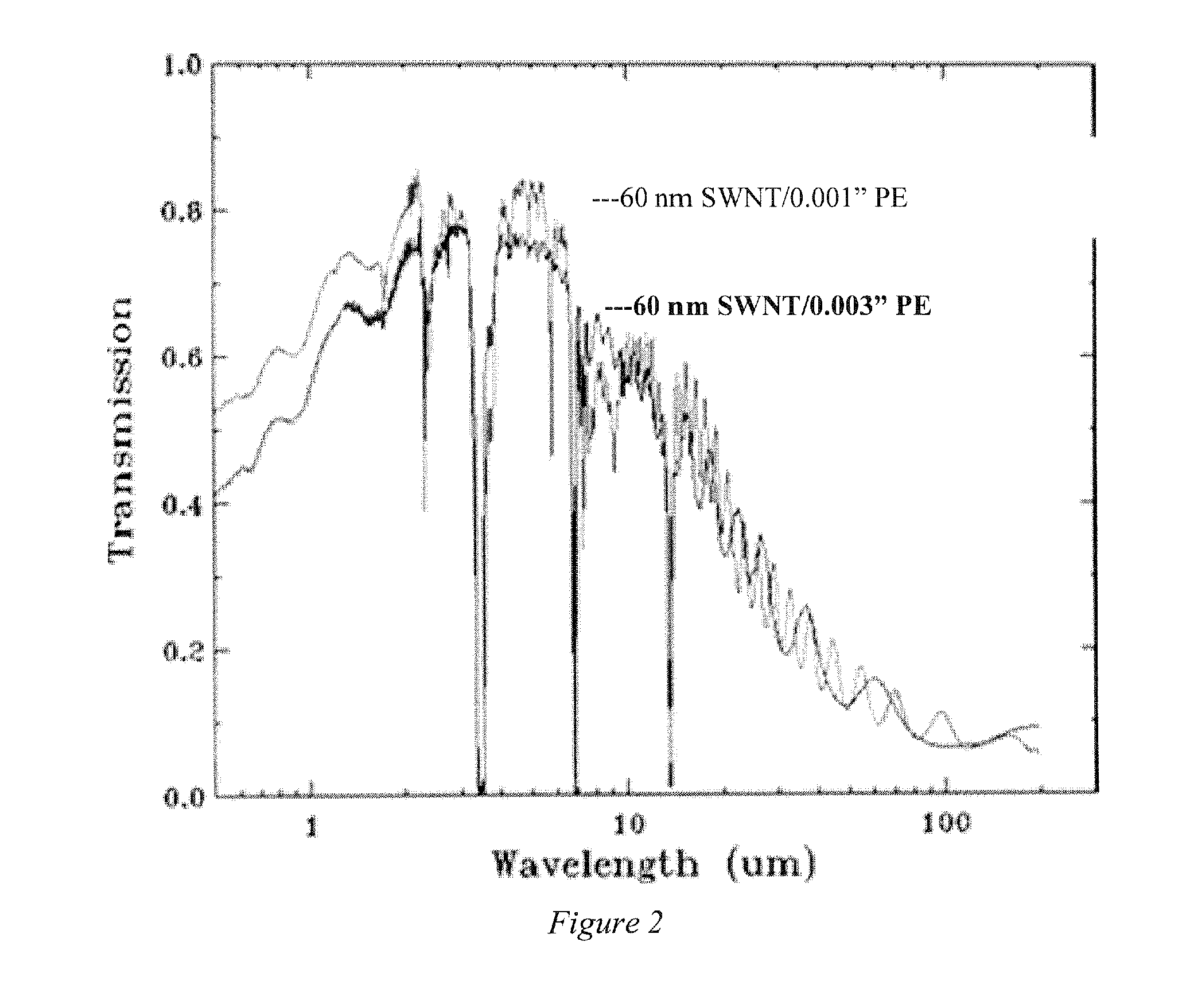
[0015]Embodiments of the invention are directed to electrochromic devices (ECDs) allowing control of IR absorbance or reflection independently of visible light or simultaneously with the visible modulation. The device can be free-standing or can be a laminate that can be attached to a surface of another device. For example, in one embodiment of the invention, the substrate upon which an ECD is deposited can be a glass or a plastic that constitutes the majority of the mass of an existing window. Single walled nanotube (SWNT) films have been developed for applications as transparent conductors, as disclosed in U.S. Pat. No. 7,261,852, which is incorporated herein by reference. FIG. 1 shows the transmittance spectrum of a free-standing 150 nm thick film of SWNTs ranging from the far IR to the UV. A majority of solar heating results from absorbed solar radiation in the 400 to 1250 cm−(8-25 micron) region as indicated in FIG. 1. A relatively thick SWNT film exhibits 50 to 80% transmittan...


PUM


Abstract

An electrochromic device (ECD) includes an electrochromic cell and, optionally, one or more additional electrochromic cells where all cells are parallel, and where at least one of the electrodes of one of the cells comprises a single-walled carbon nanotube (SWNT) film The electrochromic cells allow the control of transmittance of two or more different portions of the electro-magnetic spectrum through the ECD. One cell can control the transmittance of visible radiation while the other cell can control the transmittance of IR radiation. The ECD can be employed as a “smart window” to control the heat and light transmission through the window. The ECD can be in the form of a laminate that can be added to an existing window.

Description

CROSS-REFERENCE TO RELATED APPLICATION[0001]The present application claims the benefit of U.S. Provisional Application Ser. No. 61 / 503,015, filed Jun. 30, 2011, which is hereby incorporated by reference herein in its entirety, including any figures, tables, or drawings.BACKGROUND OF INVENTION[0002]Annually, about four percent of the total U.S. energy consumption results from window inefficiencies due to poor insulation and high transmission of solar radiation that allows an undesired heat gain or loss in the building that increases cooling or heating costs. The removal or covering of windows requires an increase in costs for lighting and reduces the aesthetics and other benefits of natural light that have been demonstrated to increase a workforce's productivity and sense of well-being. Where blinds are used to avoid disruptive glare, frequently they are not reopened when the glare ceases.[0003]To address these shortcomings, dynamic windows are at the forefront of energy efficient wi...

Claims


Application Information

Patent Timeline
IPC IPC(8): G02F1/163G01J1/44G02F1/157G01J1/04
CPCG02F1/163B82Y99/00Y10S977/742G01J1/44G02F1/157G01J1/0407B82Y20/00B82Y30/00G02F1/155G02F2001/1536G02F2201/16G02F2201/58G02F2202/28G02F2202/36G02F2203/11G02F1/15165Y02B80/00Y02A30/24
Inventor REYNOLDS, JOHN R.WALCZAK, RYAN M.RINZLER, ANDREW GABRIELVASILYEVA, SVETLANA V.DYER, AUBREY LYNN
Owner UNIV OF FLORIDA RES FOUNDATION INC
Learn More