Technique for storing shared vertices

a technology of shared vertices and vertices, applied in image memory management, digital computers, instruments, etc., can solve the problems of reducing the speed with which a graphics scene may be rendered, consuming gpu resources inefficiently, and millions of copies of redundant data, so as to increase the overall processing efficiency and conserve processing unit resources

Active Publication Date: 2014-06-26
NVIDIA CORP
View PDF2 Cites 26 Cited by
  • Summary
  • Abstract
  • Description
  • Claims
  • Application Information

AI Technical Summary

Benefits of technology

[0010]One advantage of the disclosed approach is that redundant copies of vertex data are not stored in either the vertex buffers local to the different geometry shading units or the global vertex buffer since the vertex data is indexed, thereby conserving processing unit resources and increasing overall processing efficiency.

Problems solved by technology

However, this approach is problematic because a typical graphics scene may include millions of shared vertices.
Consequently, a conventional geometry shading unit may store millions of copies of redundant data.
Processing this redundant data consumes GPU resources inefficiently and may reduce the speed with which a graphics scene may be rendered.

Method used


Image

  • Technique for storing shared vertices
  • Technique for storing shared vertices
  • Technique for storing shared vertices

Examples


Embodiment Construction

[0022]In the following description, numerous specific details are set forth to provide a more thorough understanding of the present invention. However, it will be apparent to one of skill in the art that the present invention may be practiced without one or more of these specific details.

System Overview

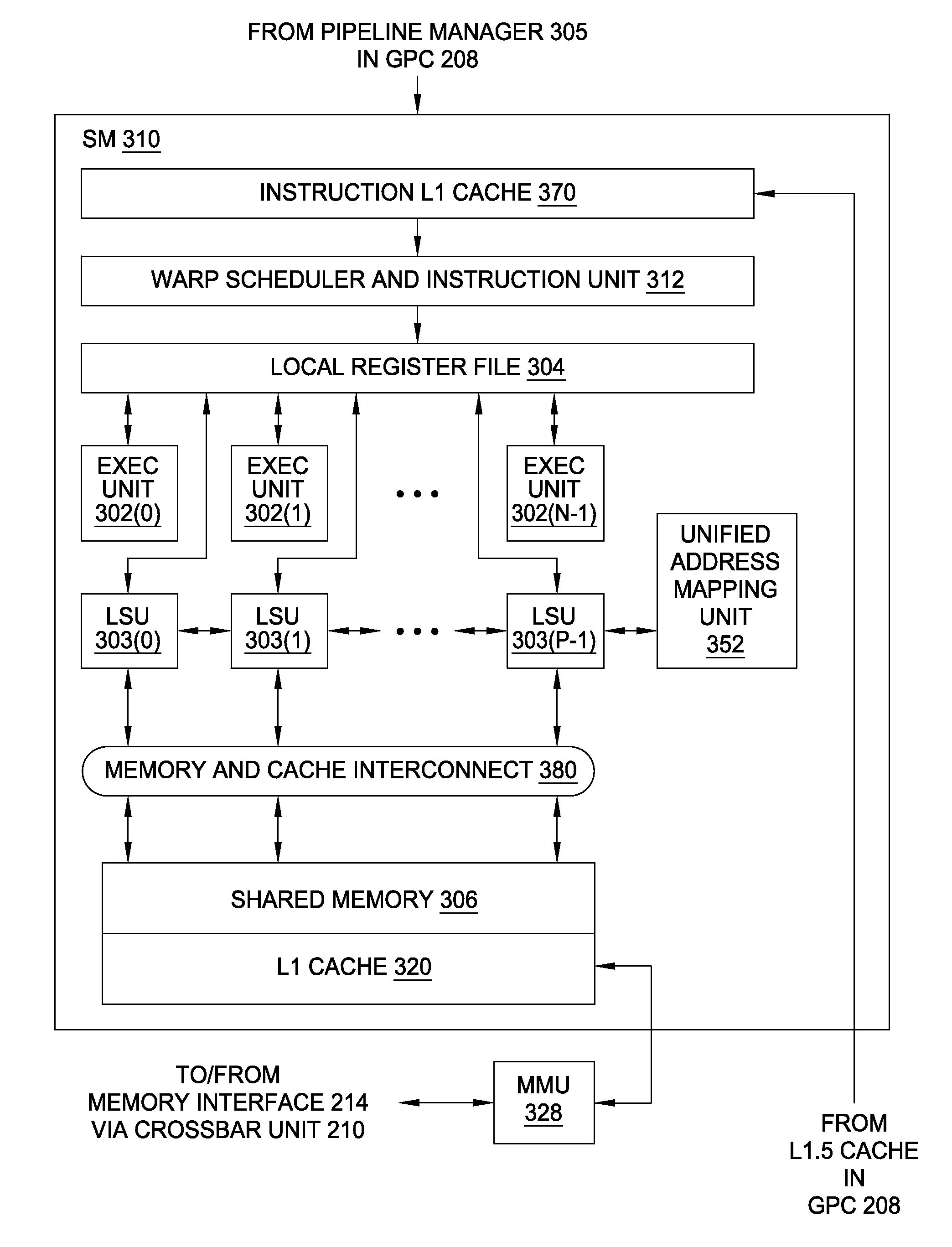
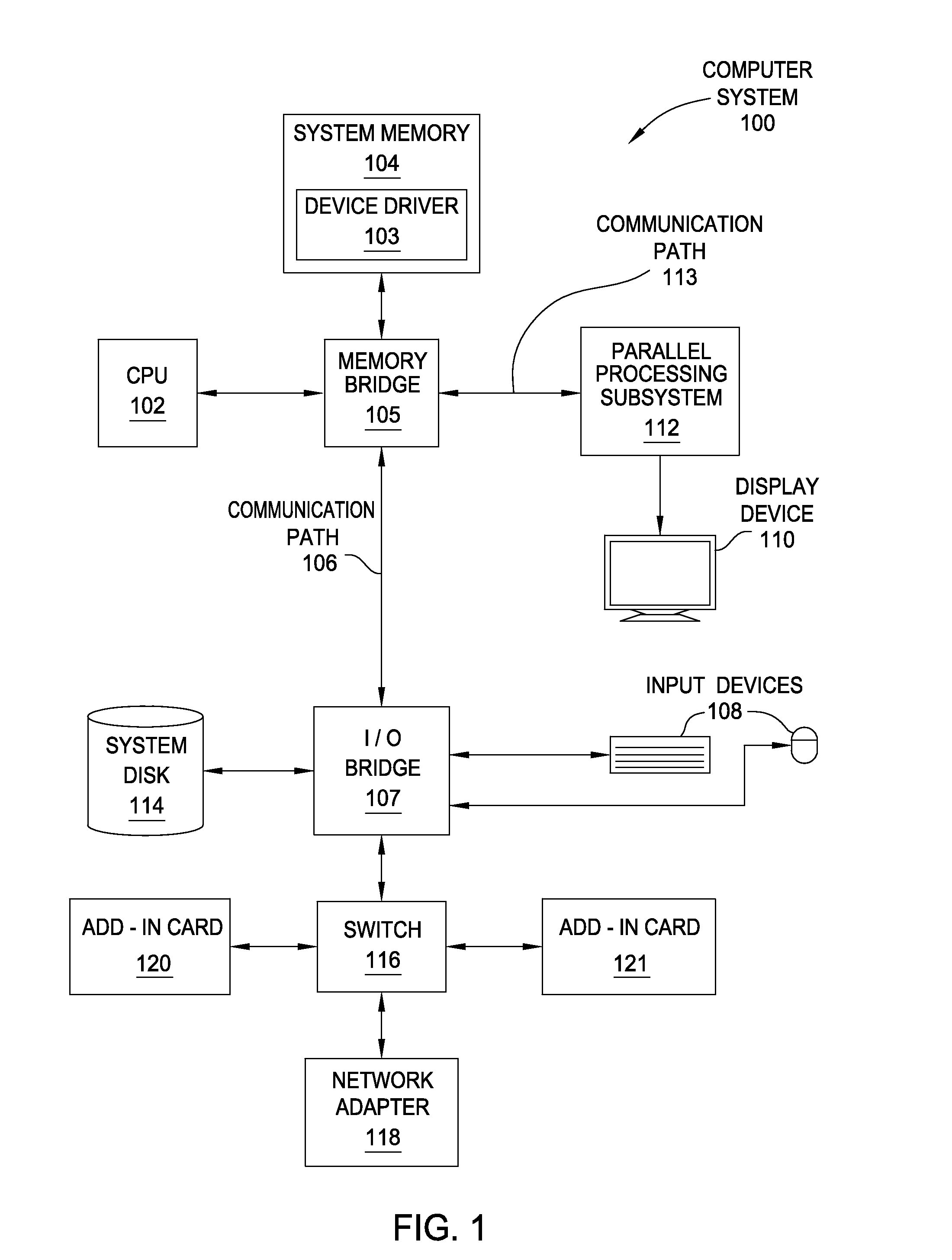
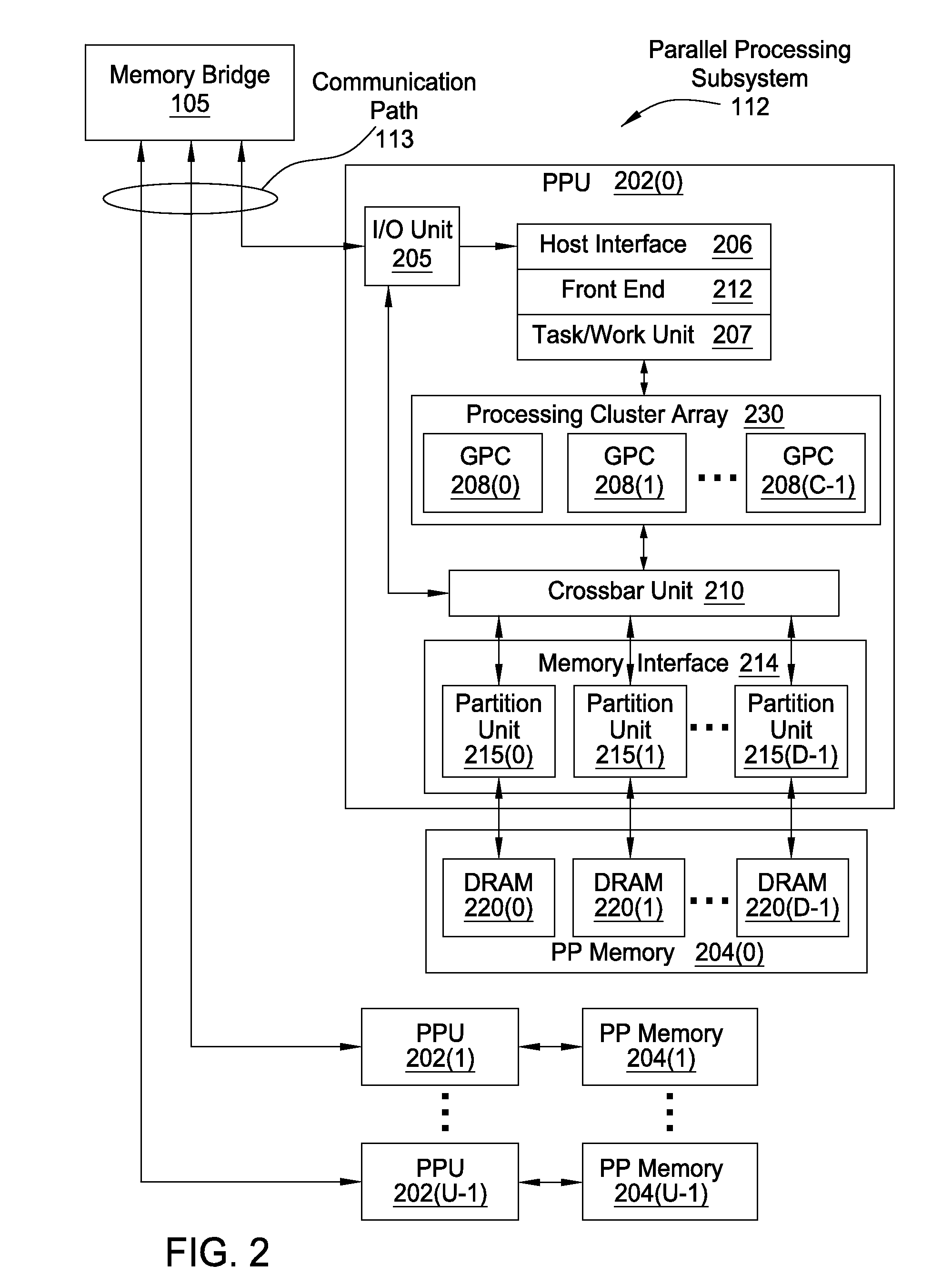
[0023]FIG. 1 is a block diagram illustrating a computer system 100 configured to implement one or more aspects of the present invention. Computer system 100 includes a central processing unit (CPU) 102 and a system memory 104 communicating via an interconnection path that may include a memory bridge 105. Memory bridge 105, which may be, e.g., a Northbridge chip, is connected via a bus or other communication path 106 (e.g., a HyperTransport link) to an I / O (input / output) bridge 107. I / O bridge 107, which may be, e.g., a Southbridge chip, receives user input from one or more user input devices 108 (e.g., keyboard, mouse) and forwards the input to CPU 102 via communication path 106 and m...


PUM


Abstract

A graphics processing unit includes a set of geometry processing units each configured to process graphics primitives in parallel with one another. A given geometry processing unit generates one or more graphics primitives or geometry objects and buffers the associated vertex data locally. The geometry processing unit also buffers different sets of indices to those vertices, where each such set represents a different graphics primitive or geometry object. The geometry processing units may then stream the buffered vertices and indices to global buffers in parallel with one another. A stream output synchronization unit coordinates the parallel streaming of vertices and indices by providing each geometry processing unit with a different base address within a global vertex buffer where vertices may be written. The stream output synchronization unit also provides each geometry processing unit with a different base address within a global index buffer where indices may be written.

Description

BACKGROUND OF THE INVENTION[0001]1. Field of the Invention[0002]The present invention generally relates to processing graphics data and, more specifically, to a technique for storing shared vertices.[0003]2. Description of the Related Art[0004]A conventional graphics processing unit (GPU) typically implements a graphics processing pipeline that includes a sequence of graphics processing stages. At each stage in the graphics processing pipeline, the GPU may perform one or more different graphics-oriented processing operations. For example, at one stage, the GPU could assemble a set of primitives that represent a graphics scene, and at a subsequent stage the GPU could perform shading operations with vertices associated with that set of primitives. Finally, the GPU could rasterize those vertices into pixels that represent the graphics scene.[0005]A GPU that implements a conventional graphics processing pipeline, such as that described in the above example, typically includes a geometry...

Claims


Application Information

Patent Timeline
Patent Type & Authority Applications(United States)
IPC IPC(8): G09G5/00
CPCG06T1/60G06T15/005G09G5/001
Inventor DULUK, JR., JEROME F.HAKURA, ZIYAD S.MORETON, HENRY PACKARD
Owner NVIDIA CORP
Why Eureka
Try Eureka