Heavy radial neutron reflector for pressurized water reactors

Active Publication Date: 2014-06-26
WESTINGHOUSE ELECTRIC CORP
View PDF9 Cites 7 Cited by
  • Summary
  • Abstract
  • Description
  • Claims
  • Application Information

AI Technical Summary

Problems solved by technology

However, since these plates are relatively thin, most of the neutrons escaping radially from the core migrate into the large volume of water between the baffle plates and the core barrel which absorbs or thermalizes the neutrons with very little reflection.

Method used


Image

  • Heavy radial neutron reflector for pressurized water reactors
  • Heavy radial neutron reflector for pressurized water reactors
  • Heavy radial neutron reflector for pressurized water reactors

Examples


Embodiment Construction

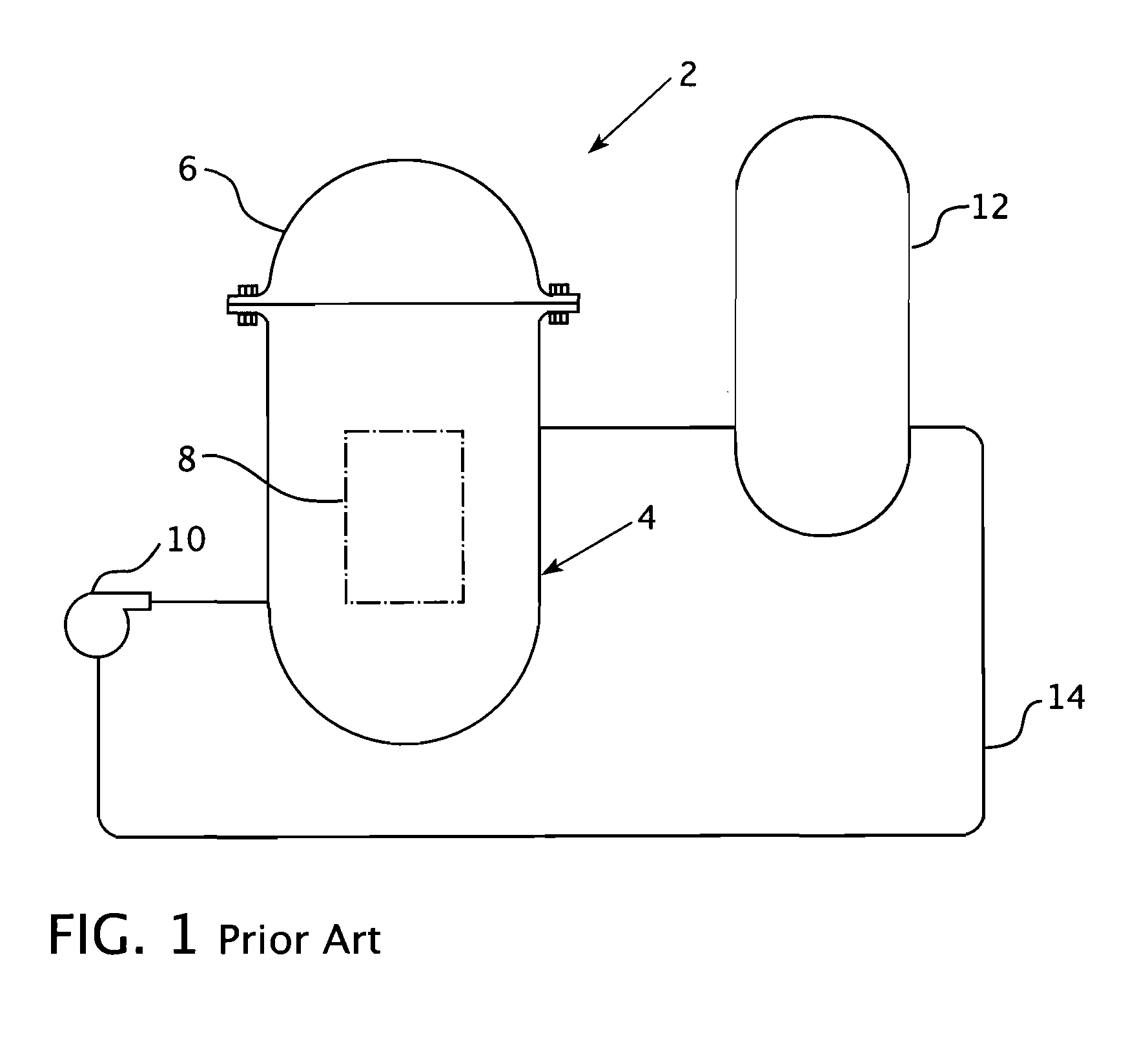
[0033]Referring now to the drawings, FIG. 1 shows a simplified nuclear reactor primary system 2, including a generally cylindrical reactor pressure vessel 4 having a closure head 6 enclosing a nuclear core 8. A liquid reactor coolant, such as water, is pumped into the vessel 4 by the pump 10 through the core 8 where heat energy is absorbed and is discharged to a heat exchanger 12 typically referred to as a steam generator, in which heat is transferred to a utilization circuit (not shown) such as a steam driven turbine generator. The reactor coolant is then returned to the pump 10 completing the primary loop. Typically, a plurality of the above described loops are connected to a single reactor vessel 4 by the reactor coolant piping 14.

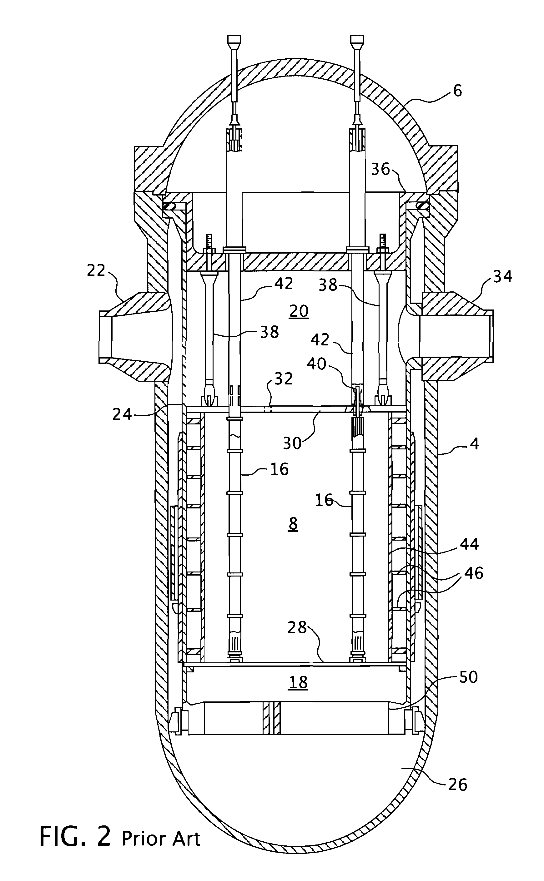
[0034]A conventional reactor design is shown in more detail in FIGS. 2, 3 and 4. In addition to the core 8 comprised of a plurality of parallel, vertically co-extending fuel assemblies 16, for purposes of this description, the other internal structures ...


PUM


Abstract

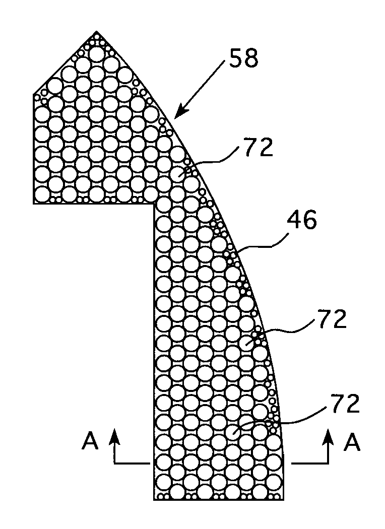
A heavy radial neutron reflector for a pressurized water reactor that employs elongated lengths of round bar stock closely packed in either a triangular or rectangular array extending between former plates of a core shroud between the core barrel and the baffle plates which outline the periphery of the reactor core and are formed in axial and circumferential modules. Flow channels are formed in the long gaps between the adjacent round bar stock that communicates cooling water that enters through the core barrel at the top of the shroud and flows down through openings in the former plates to the bottom of the neutron reflector where it exits through a lower baffle orifice to join other cooling water flowing up through the lower core support plate.

Description

BACKGROUND[0001]1. Field[0002]This invention relates in general to the field of pressurized light water nuclear reactors and, in particular, to radial neutron reflectors which surround the nuclear core for improved neutron economy to lower fuel costs and reduce the radiation dose on the pressure vessel.[0003]2. Description of Related Art[0004]The fission reactions in a nuclear reactor generate heat and release neutrons which produce additional fission reactions in the nuclear fuel. The fissile material is massed in the reactor such that the neutron flux density is sufficient to maintain a sustained fission process. In a commercial reactor, pellets of the fissile material are encased in Zircoloy rods mounted in modular, elongated fuel assemblies which are generally square in cross section. A large number of these square, elongated fuel assemblies are massed to form a generally cylindrical reactor core which is housed inside the cylindrical stainless steel core barrel between horizont...

Claims


Application Information

Patent Timeline
Patent Type & Authority Applications(United States)
IPC IPC(8): G21C11/06
CPCG21C11/06Y02E30/30
Inventor HARKNESS, ALEXANDER W.
Owner WESTINGHOUSE ELECTRIC CORP
Why Eureka
Try Eureka