Radiation imaging system, communication method of radiation imaging system, and radiographic image detecting device

a radiation imaging and communication method technology, applied in the direction of material analysis using wave/particle radiation, instruments, applications, etc., can solve the problems of reducing the quality of x-ray images, requiring rapid communication of aec signals between source control devices and x-ray image detecting devices, and unnecessary radiation exposure of patients, etc., to achieve the effect of optimizing the operating environmen

Inactive Publication Date: 2014-06-26
FUJIFILM CORP
View PDF3 Cites 15 Cited by
  • Summary
  • Abstract
  • Description
  • Claims
  • Application Information

AI Technical Summary

Benefits of technology

[0029]According to the present invention, the AEC signal is communicated at the relatively high communication speed, and the signal other than the AEC signal is communicated wirelessly at the communication speed lower than the communication speed of the AEC signal. Therefore, it is possible to provide the communication method of the radiation imaging system and the radiographic image detecting device that can make communication in an optimal operating environment.

Problems solved by technology

This is because a delay in a process of stopping the X-ray emission reduces the quality of the X-ray image and causes unnecessary radiation exposure of the patient, owing to an excessive radiation dose beyond an appropriate value.
Therefore, the communication of the AEC signal between the source control device and the X-ray image detecting device requires rapidity.
In the case of using the electronic cassette in a detached state from the imaging table or carrying about the electronic cassette, the complicated routing of the communication cable adversely affects the handleability and the portability of the electronic cassette and the console.

Method used


Image

  • Radiation imaging system, communication method of radiation imaging system, and radiographic image detecting device
  • Radiation imaging system, communication method of radiation imaging system, and radiographic image detecting device
  • Radiation imaging system, communication method of radiation imaging system, and radiographic image detecting device

Examples


first embodiment

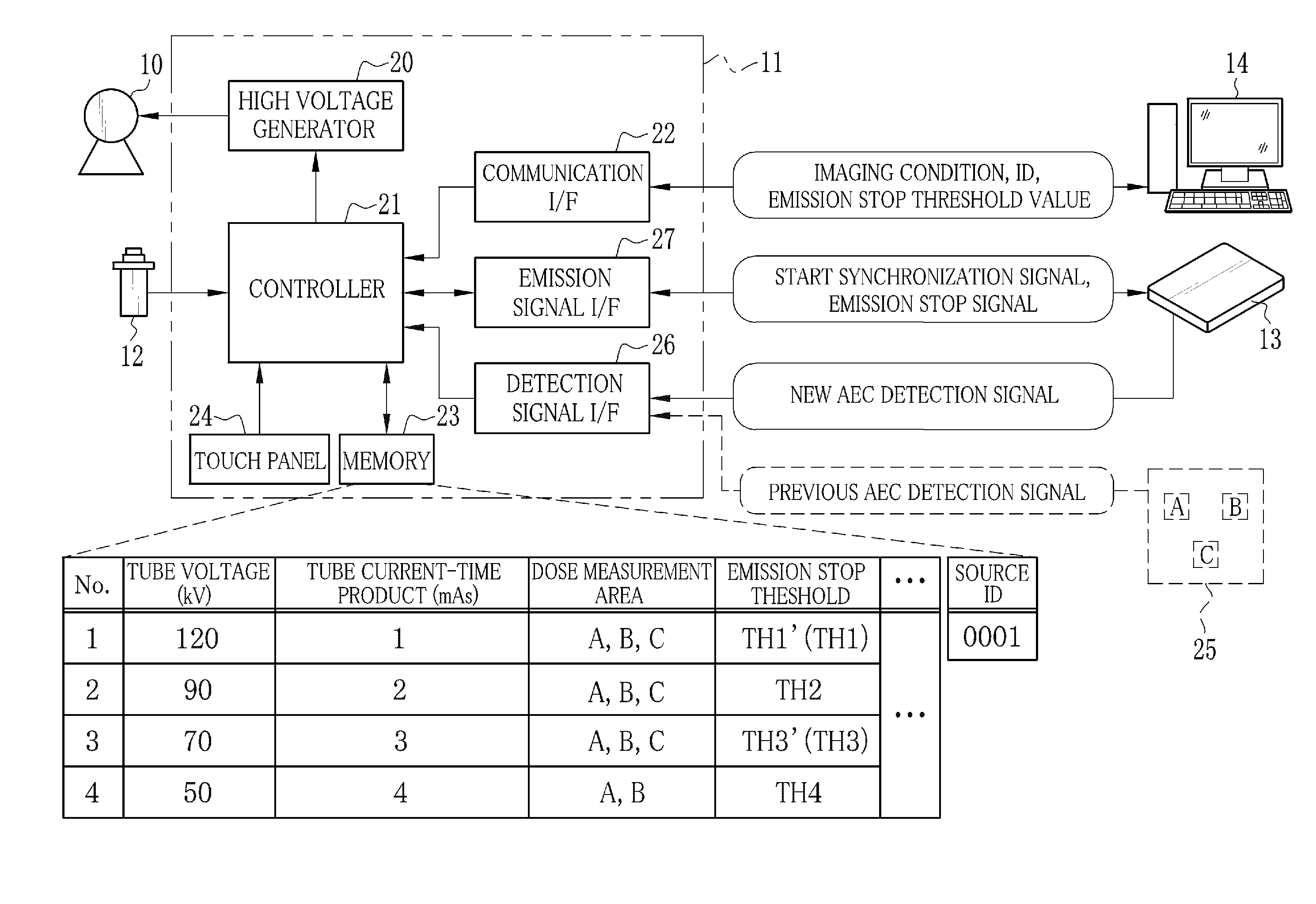
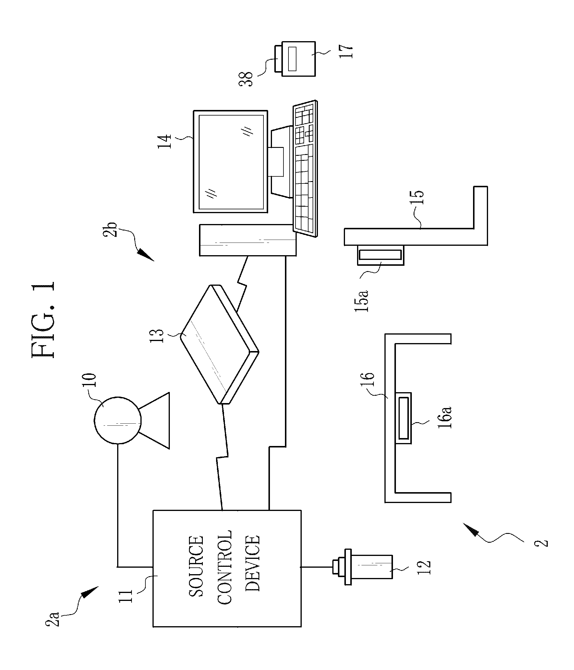
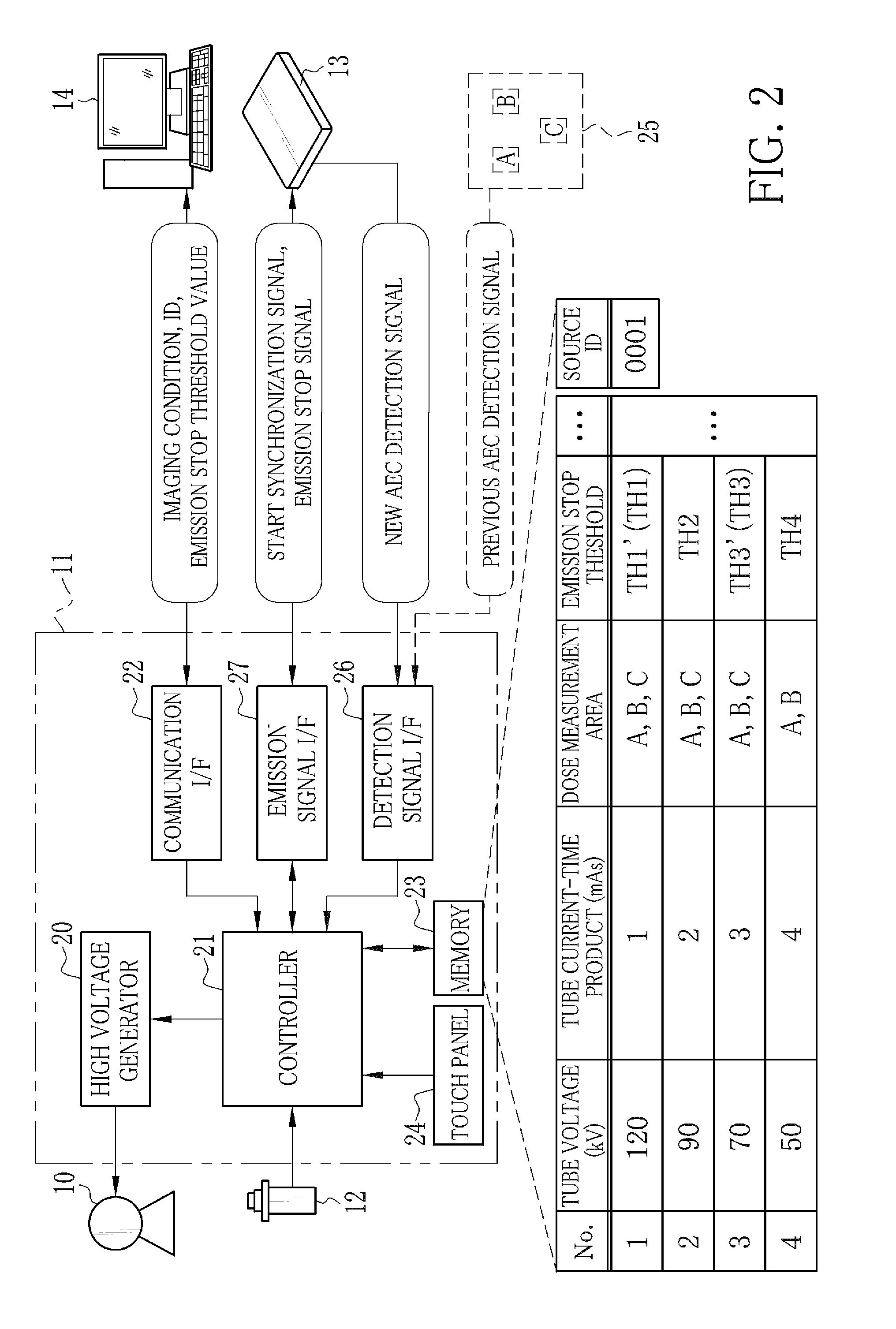
[0053]In FIG. 1, an X-ray imaging system (radiation imaging system) 2 includes an X-ray source (radiation source) 10 containing an X-ray tube for radiating X-rays, a source control device 11 for controlling the operation of the X-ray source 10, an emission switch 12 for commanding a start of X-ray emission, an electronic cassette (radiographic image detecting device) 13 for detecting the X-rays passed through an object and outputting an X-ray image, a console 14 for performing operation control of the electronic cassette 13, an image process of the X-ray image, and display of the X-ray image, an imaging stand 15 for imaging the object in a standing position, and an imaging table 16 for imaging the object in a lying position. The X-ray source 10, the source control device 11, and the emission switch 12 compose an X-ray generating apparatus 2a. The electronic cassette 13 and the console 14 compose an X-ray imaging apparatus 2b. In addition to above, the X-ray imaging system 2 is provi...

second embodiment

[0167]In the above first embodiment, the optical wireless communications is used as an example of high speed communications of the detection signal or the emission stop signal for the AEC between the source control device 11 and the electronic cassette 13, and the wireless LAN or the like is used as an example of low speed wireless communications of various types of information and signals other than the detection signal and the emission stop signal for the AEC between the electronic cassette 13 and the console 14. However, ad-hoc communications may be used in the former communications, and infrastructure communications may be used in the latter communications.

[0168]The ad-hoc communications is a method in which wireless communication devices (the source control device 11 and the electronic cassette 13) have a routing function of a wireless communication channel and each wireless communication device performs communication on an autonomous basis. Thus, the ad-hoc communications is e...

third embodiment

[0173]In the above first and second embodiments, the controller 41 is in charge of controlling the operation of parts including the gate driver 53, the signal processor 54, and the AEC unit 67. The antenna 37 and the socket 39 for making communication with the console 14, and the detection signal I / F 80 and the emission signal I / F 81 for making communication with the source control device 11 are disposed integrally into one communication unit 40. Thus, a process related to the communication with the console 14 conflicts with a process related to the communication with the source control device 11 in the controller 41, or the communication with the console 14 overlaps with the communication with the source control device 11 in the controller 41. As a result, there is a possibility of delaying the transmission timing of the detection signal or the emission stop signal from the detection signal I / F 80 or the emission signal I / F 81.

[0174]Therefore, in the electronic cassette 13 accordin...


PUM


Abstract

A communication section having a relatively high communication speed is used for communicating a detection signal or an emission stop signal between a source control device and an electronic cassette. The detection signal is outputted from a detection pixel of the electronic cassette. The emission stop signal depends on a comparison result between an integrated value of the detection signal and an emission stop threshold value. On the other hand, a wireless communication section having a lower communication speed than that of the detection signal and the emission stop signal is used for communicating image data and the like between the electronic cassette and a console.

Description

BACKGROUND OF THE INVENTION[0001]1. Field of the Invention[0002]The present invention relates to a radiation imaging system, a communication method of the radiation imaging system, and a radiographic image detecting device.[0003]2. Description Related to the Prior Art[0004]In a medical field, an X-ray imaging system using X-rays, as a kind of radiation, is known. The X-ray imaging system is constituted of an X-ray generating apparatus for generating the X-rays and an X-ray imaging apparatus, which receives the X-rays and takes an X-ray image. The X-ray generating apparatus includes an X-ray source for emitting the X-rays to an object, a source control device for controlling the operation of the X-ray source, and an emission switch for inputting an emission start command of the X-rays. The X-ray imaging apparatus includes an X-ray image detecting device and a console. The X-ray image detecting device detects the X-ray image upon receiving the X-rays passed through the object. The con...

Claims


Application Information

Patent Timeline
Patent Type & Authority Applications(United States)
IPC IPC(8): A61B6/00
CPCA61B6/4233A61B6/4283A61B6/548A61B6/545A61B6/56A61B6/58A61B6/542
Inventor KITAGAWA, YUSUKEKAMIYA, TAKESHIKUWABARA, TAKESHITAJIMA, TAKASHI
Owner FUJIFILM CORP
Why Eureka
Try Eureka