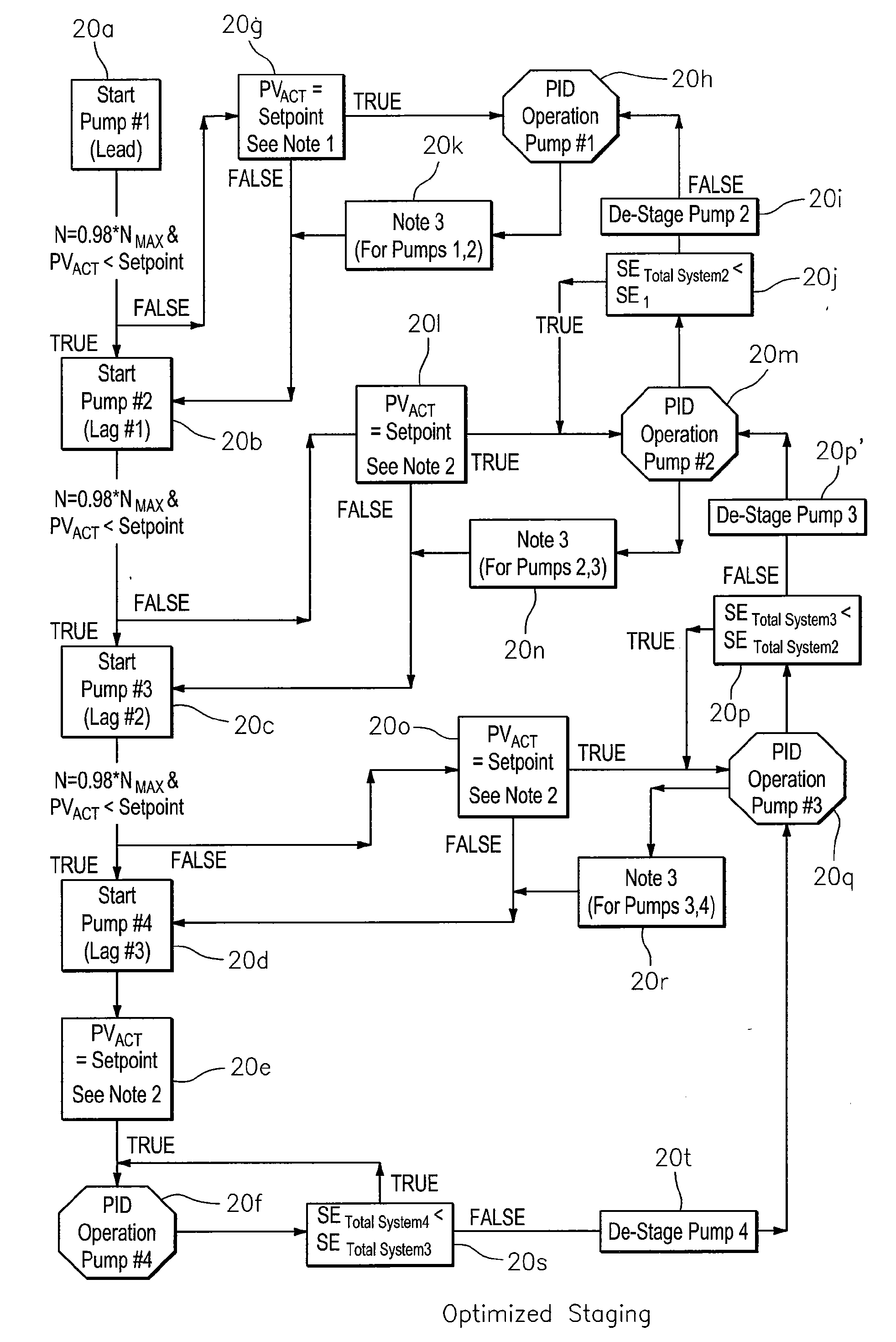
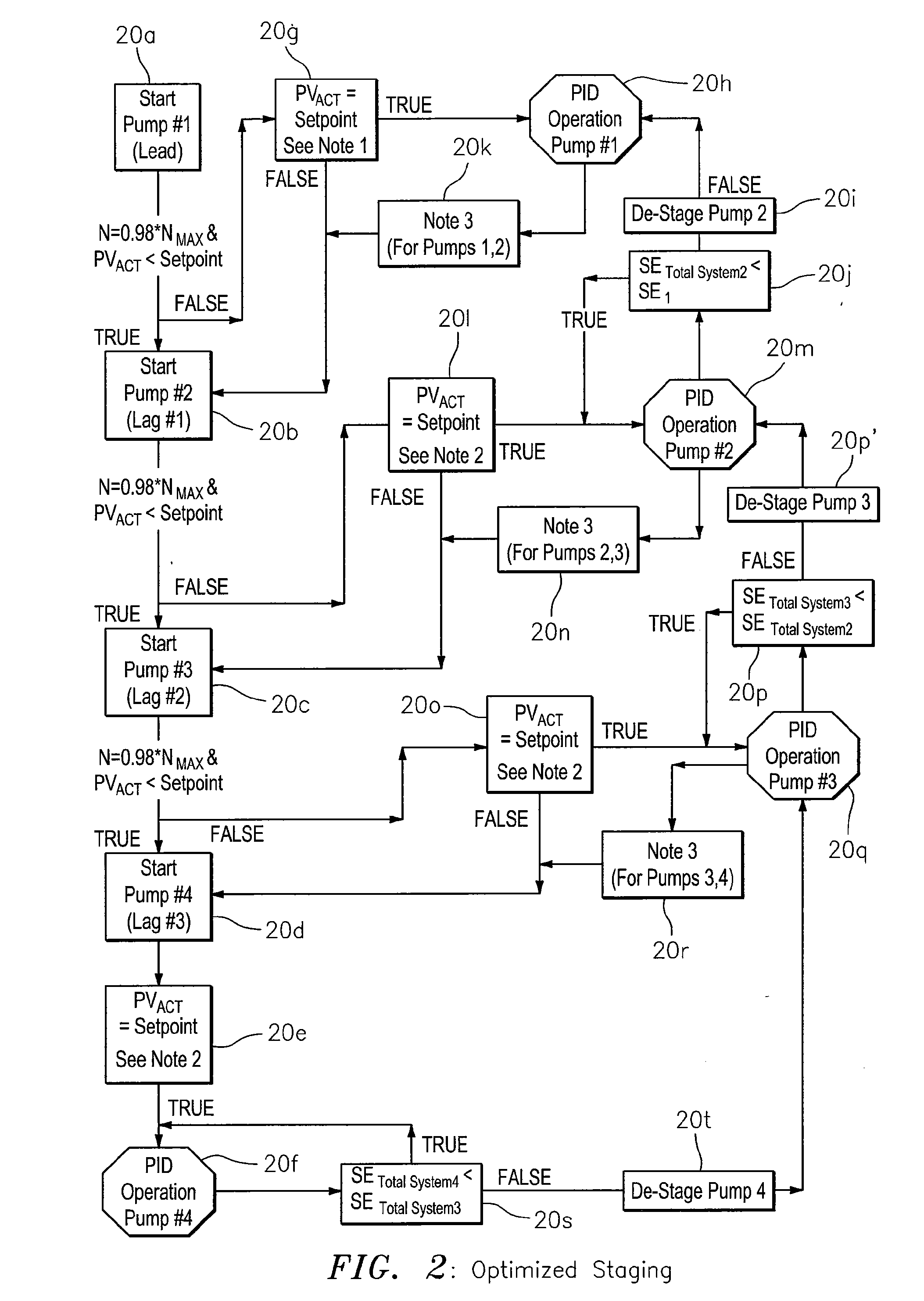
Optimized technique for staging and de-staging pumps in a multiple pump system
a technology of multiple pump system and staging technique, which is applied in the direction of flow control using electric means, non-positive displacement fluid engines, instruments, etc., can solve the problems of multiple pump system setup, cumbersome and time-consuming, and difficult to determine the appropriate de-stage value without trial, so as to improve the overall system reliability, the effect of reducing the cost and being easy to setup
- Summary
- Abstract
- Description
- Claims
- Application Information
AI Technical Summary
Benefits of technology
Problems solved by technology
Method used
Image

Examples
Embodiment Construction
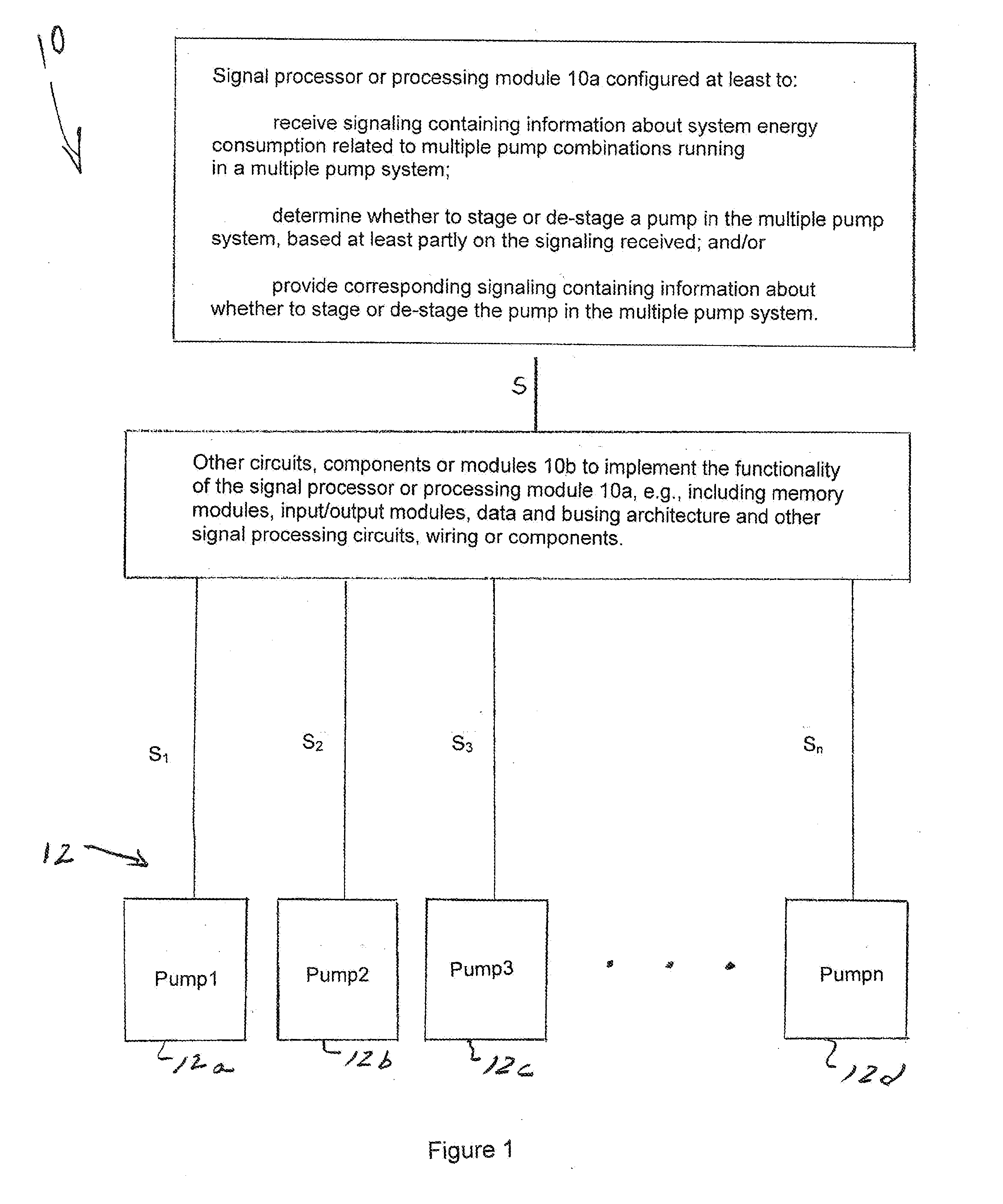
[0017]According to some embodiments, the present invention may include, or take the form of, apparatus featuring a signal processor or processing module configured at least to:[0018]receive signaling containing information about system energy consumption related to multiple pump combinations running in a multiple pump system; and[0019]determine whether to stage or de-stage a pump in the multiple pump system, based at least partly on the signaling received.
[0020]The present invention may also include one or more of the following features:
[0021]The signal processor or processing module may be configured to provide corresponding signaling containing information about whether to stage or de-stage the pump in the multiple pump system.
[0022]The signaling may be received from one or more pumps in a multiple pump system.
[0023]The apparatus may include the one or more pumps in a multiple pump system.
[0024]The signal processor or processing module may be configured to implement control logic ...
PUM
 Abstract
Description
Claims
Application Information
 - Generate Ideas
- Intellectual Property
- Life Sciences
- Materials
- Tech Scout
- Unparalleled Data Quality
- Higher Quality Content
- 60% Fewer Hallucinations
Browse by: Latest US Patents, China's latest patents, Technical Efficacy Thesaurus, Application Domain, Technology Topic, Popular Technical Reports.
© 2025 PatSnap. All rights reserved.Legal|Privacy policy|Modern Slavery Act Transparency Statement|Sitemap|About US| Contact US: help@patsnap.com