Low clock-power integrated clock gating cell

Active Publication Date: 2014-07-03
TEXAS INSTR INC
View PDF11 Cites 22 Cited by
  • Summary
  • Abstract
  • Description
  • Claims
  • Application Information

AI Technical Summary

Problems solved by technology

In advanced digital designs, several clock gating cells

Method used


Image

  • Low clock-power integrated clock gating cell
  • Low clock-power integrated clock gating cell
  • Low clock-power integrated clock gating cell

Examples


Embodiment Construction

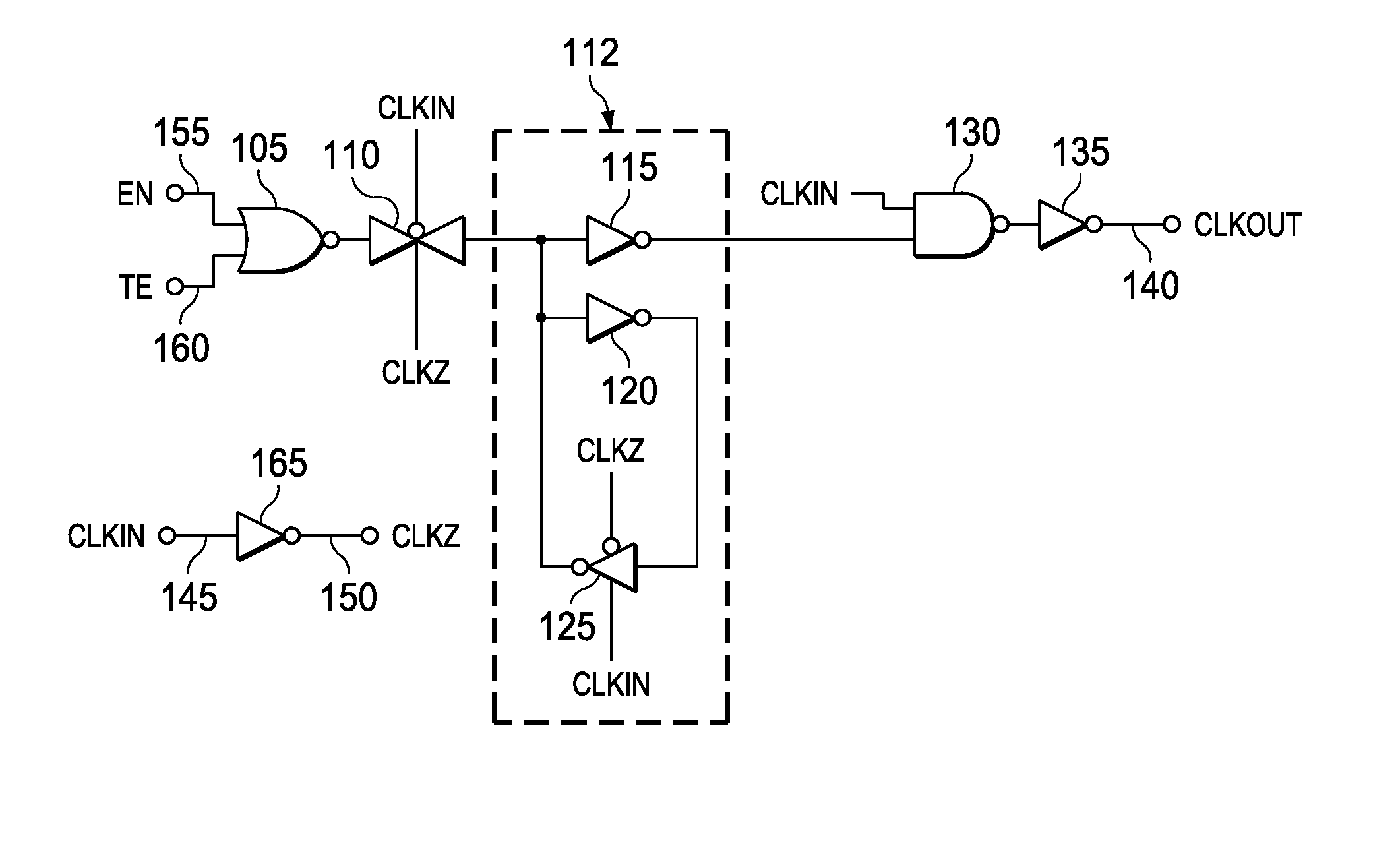
[0013]FIG. 1 illustrates a schematic of an ICG. The ICG includes a NOR gate 105 that receives a test enable signal 160 and an enable signal 155. The NOR gate 105 is coupled to a transmission gate 110. The transmission gate 110 receives a clock input CLKIN 145 and an inverted clock signal CLKZ 150. The inverted clock signal 150 is generated through an inverter 165 that receives the CLKIN 145 and outputs the inverted clock signal CLKZ 150. The output of the transmission gate is coupled to a latch 112 that includes an inverter 115 and back-to-back inverters 120 and 125. The inverter 125 is a tri-state inverter. Output of the latch 112 is coupled to a NAND gate 130. The clock input CLKIN 145 is also given as another input to the NAND gate 130. An output of the NAND gate 130 is coupled to an inverter 135 which generates the clock output CLKOUT on a line 140.

[0014]The operation of the ICG of FIG. 1 is explained now. Consider an example when the enable signal 155 is at logic 1 and the test...


PUM


Abstract

In an integrated clock gating (ICG) cell a latch is coupled to a NOR gate. The NOR gate receives an enable signal. The latch is configured to generate a latch output in response to the state of the enable signal. The latch includes a tri-state inverter. A NAND gate is coupled to the latch and the NAND gate is configured to generate an inverted clock signal in response to the latch output and a clock input.

Description

TECHNICAL FIELD[0001]Embodiments of the disclosure relate to integrated clock gating (ICG) cells in an integrated circuit (IC).BACKGROUND[0002]Integrated clock gating (ICG), in digital IC designs, is used to reduce power consumption by preventing individual flip flops from switching between logic states when not in use. In integrated clock gating, the flip flops which are not contributing to the functionality of the circuit are selectively inactivated. The ICG cells are activated or inactivated based on certain conditions. The conditions for disabling the clock cells are a design choice. In advanced digital designs, several clock gating cells are used which results in increased power consumption. A comparison of percentage of power consumption between the units in an example IC are logic implementation consuming 29%, flip flops consuming 27%, RAM consuming 18%, clock tree consuming 16% and the ICG consuming 10% of the total power. It is apparent that if the power consumption of one ...

Claims


Application Information

Patent Timeline
IPC IPC(8): H03K19/00
CPCH03K19/0016
Inventor GURUMURTHY, GIRISHANKARVASISHTA, MAHESH RAMDAS
Owner TEXAS INSTR INC
Why Eureka
Try Eureka