Cleaning device for cleaning a surface comprising a brush and a squeegee element

a cleaning device and surface technology, applied in the direction of vacuum cleaners, carpet cleaners, domestic applications, etc., can solve the problems of not being able to pick up water from the floor to be cleaned, not being able to dry the floor, and not being able to include a vacuum source, so as to achieve optimal cleaning performance of the rotatable brush, improve the cleaning effect, and improve the cleaning

Active Publication Date: 2014-07-10
KONINKLIJKE PHILIPS ELECTRONICS NV
View PDF5 Cites 12 Cited by
  • Summary
  • Abstract
  • Description
  • Claims
  • Application Information

AI Technical Summary

Benefits of technology

[0053]It is to be noted that the linear mass density as mentioned, i.e. the linear mass density in grams per 10 km, is also denoted as Dtex value.
[0054]The experiments carried out by the applicant have proven that a Dtex value in the above-mentioned range appears to be technically possible and that good cleaning results can be obtained therewith. However, it has shown that cleaning results can be further improved by applying brush elements with an even lower upper limit of the Dtex value, such as a Dtex value of 125, 50, 20 or even 5 (in g/km).
[0055]The combination of the linear mass density of the brush elements and the above-mentioned accelerations at the tips of the brush elements is a combination which yields optimal cleaning performance of the rotatable brush, wherein practically all dirt particles and spilled liquid encountered by the brush are picked-up by the brush elements and expelled at a position inside the nozzle housing. Naturally, effective pick-up of particles and liquid is advantageous when it comes to cleaning, wherein both a dirt removal and a drying process are realized at the same time. An effective subsequent expelling process is advantageous in view of the fact that a re-introduction of dirt and/or liquid to the surface to be cleaned is avoided. With the brush according to the present invention in combination with the above-mentioned squeegee element and the operating parameters which are realized by the drive means, it is possible to catch particles into droplets making the particles effectively larger which enables for an easier filtering. Besides that, this parameter combination further increases the above-mentioned sealing effect at said first and second positions and, in case an above-mentioned further restriction element is

Problems solved by technology

The sweeper, however, does not include a vacuum source and is therefore not able to pick-up water from the floor to be cleaned.
The performance on drying the floor is thus rather low.
However, the performance on drying the floor is rather low, since such an agitator is not able to lift liquid from the floor.
Moving the device in an opposite backward direction would leave the floor wet, since the cleaning water which is dispersed with the brush is not removed from the squeegees in this backward stroke.
Even though such double squeegee arrangements on both sides of the brush show good cleaning results, the nozzle of these devices become fairly bulky.
This again results in a non-satisfying, limited work capability.
Especially in household appliances where often narrow corners need to be cleaned, such bulky nozzles are, due to their limited liberty of action, uncomfortable to use.
Due to the constan

Method used


Image

  • Cleaning device for cleaning a surface comprising a brush and a squeegee element
  • Cleaning device for cleaning a surface comprising a brush and a squeegee element
  • Cleaning device for cleaning a surface comprising a brush and a squeegee element

Examples


Embodiment Construction

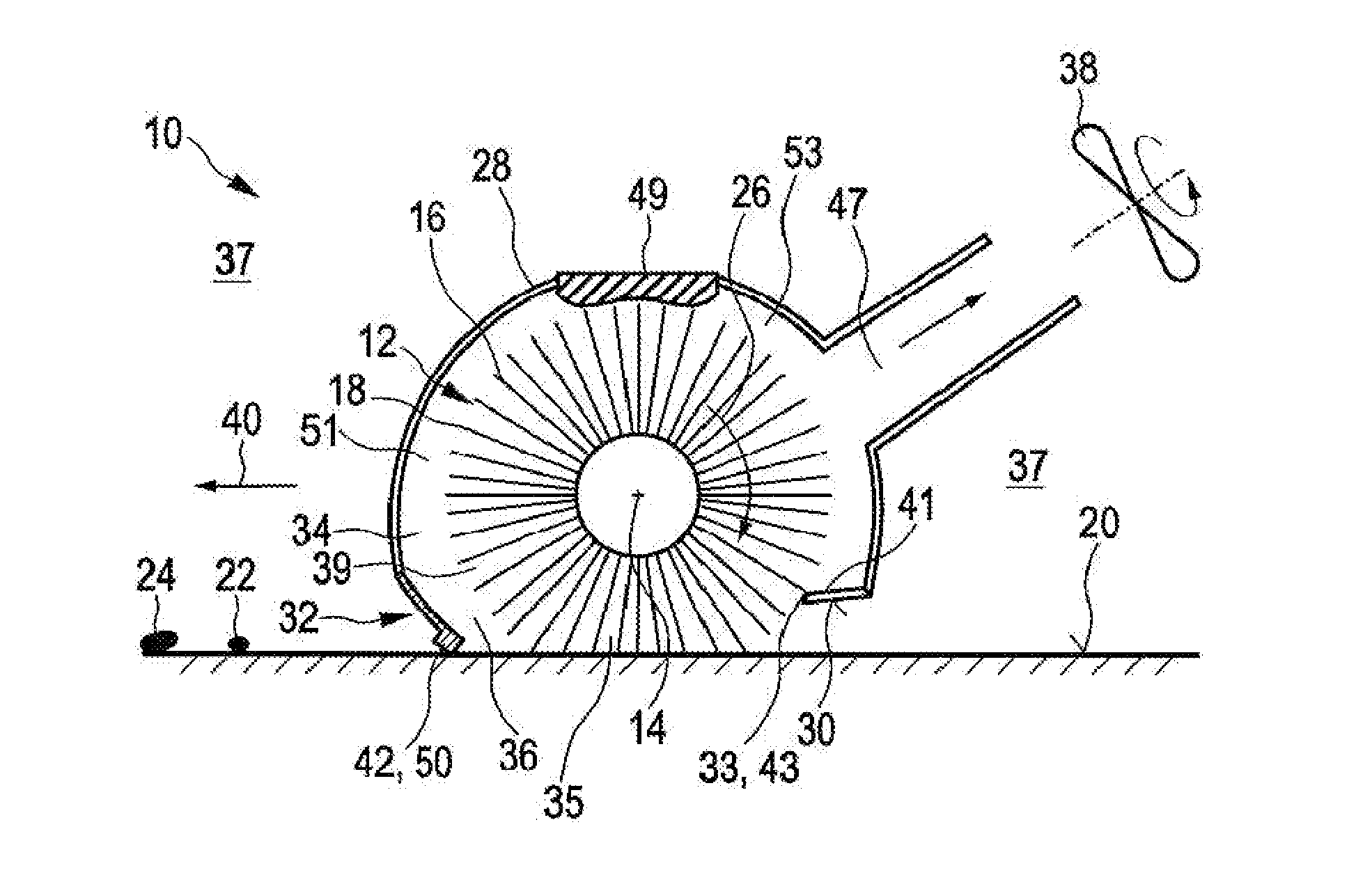
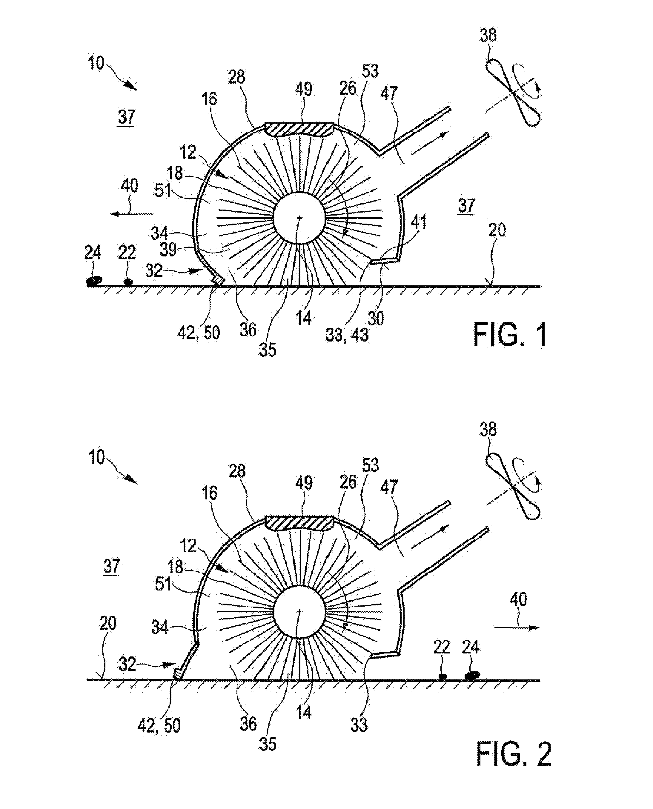
[0085]FIGS. 1 and 2 show a schematic cross-section of a first embodiment of a nozzle arrangement 10 of a cleaning device 100 according to the present invention.

[0086]In FIG. 1 the nozzle arrangement 10 is shown in a first working position, whereas in FIG. 2 the nozzle arrangement 10 is shown in a second working position. The nozzle arrangement 10 comprises a brush 12 that is rotatable about a brush axis 14. Said brush 12 is provided with flexible brush elements 16, which are preferably realized by thin microfiber hairs. The flexible brush elements 16 are substantially uniformly distributed over the periphery of the brush 12. Furthermore, the flexible brush elements 16 comprise tip portions 18 which are adapted to contact a surface to be cleaned 20 during the rotation of the brush 12 and to pick-up dirt particles 22 and liquid 24 from said surface 20 during a pick-up period when the brush elements 16 contact the surface 20.

[0087]Further, the nozzle arrangement 10 comprises a drive me...


PUM


Abstract

The present invention relates to a cleaning device for cleaning a surface (20), comprising: —a brush (12) rotatable about a brush axis (14), said brush (12) being provided with flexible brush elements (16) that are substantially uniformly distributed over the periphery of the brush (12), wherein the brush (12) is at least partly surrounded by a nozzle housing (28) and protrudes at least partially from a bottom side (30) of said nozzle housing (28), which, during use of the device (100), faces the surface to be cleaned (20), wherein the brush elements (16), during the rotation of the brush (12), substantially form a sealing with the housing (28) at a first position (33) where the brush elements (16) leave the housing (28) during the rotation of the brush (12), and contact the surface to be cleaned (20) during the rotation of the brush (12) at a second position (35) for picking up dirt particles (22) and liquid (24) from said surface (20), thereby defining a suction area (34) in a space between the brush (12), said housing (28) and said surface to be cleaned (20) which is at least partly sealed at said first and second positions (33, 35), —a single squeegee element (32) which is spaced apart from the brush (12) and attached to the bottom side (30) of the nozzle housing (28) on a side of the brush (12), where the brush elements (16) enter the housing (28) during the rotation of the brush (12), wherein said squeegee element (32) is adapted for pushing or wiping dirt particles and liquid across or off the surface to be cleaned (20) during movement of the cleaning device (100), thereby defining a suction inlet (36) between the squeegee element (32) and the brush (12) that opens into the suction area (34), —a drive means for driving the brush (12) in rotation, and —a vacuum aggregate (38) which is arranged at a suction outlet (47) of the suction area (34) for generating an under-pressure in said suction area (34) for ingesting dirt particles (22) and liquid (24) from the suction inlet (36).

Description

FIELD OF THE INVENTION[0001]The present invention relates to a cleaning device for cleaning a surface. Further, the present invention relates to a nozzle arrangement for such a cleaning device.BACKGROUND OF THE INVENTION[0002]Hard floor cleaning these days is done by first vacuuming the floor, followed by mopping it. Vacuuming removes the coarse dirt, while mopping removes the stains. From the state of the art many appliances, especially targeting the professional cleaning sector, are known that claim to vacuum and mop in one go. Appliances for the professional cleaning sector are usually specialized for big areas and perfectly flat floors. They rely on hard brushes and suction power to get water and dirt from the floor. Appliances for home use often use a combination of a hard brush and a squeegee nozzle. Like the appliances for the professional cleaning sector these products use the brush to remove stains from the floor and the squeegee in combination with an under-pressure to lif...

Claims


Application Information

Patent Timeline
IPC IPC(8): A47L9/04A47L11/40
CPCA47L9/0488A47L11/4044A47L11/4041A47L9/0477
Inventor VAN DER KOOI, JOHANNES TSEARDROUMEN, BRITTKINGMA, PIETER
Owner KONINKLIJKE PHILIPS ELECTRONICS NV
Why Eureka
Try Eureka