
Acoustic Ventilation and Respiratory Booster Machine

a technology of acoustic ventilation and a booster machine, which is applied in the direction of respirator, valve, operating means/releasing devices, etc., can solve the problems of high power limit, oscillatory rate, and hfov machines getting into a functional limitation in higher rates, so as to achieve exponential enhancement of alveolar ventilation

Inactive Publication Date: 2014-07-10
JAM MOHAMMAD R
View PDF7 Cites 38 Cited by
  • Summary
  • Abstract
  • Description
  • Claims
  • Application Information

AI Technical Summary

Benefits of technology

The patent text describes a new ventilation technique that overcomes the limitations of current methods by using sonic vibrations to improve breathing in critically ill patients. This technique involves using a device called an acoustic ventilator that creates sonic vibrations to create pressure waves in the airways, which helps to ventilation and diffusion of gases. The high-frequency ventilators that are currently available cannot generate satisfactory ventilation at frequencies above 15-20 Hz, which is necessary for effective ventilation in certain conditions like premature newborns. However, the acoustic ventilator can overcome these limitations by producing higher frequencies in the range of 180-900 Hz, allowing for better ventilation in the airways. The use of sonic energy can also prevent damage to the delicate airways and improve alveolar ventilation.

Problems solved by technology

Physical design of HFOV machines gets them into a functional limitation in higher rates in a process to be called HFV choking phenomenon.
In difficult cases of CO2 retention such as RDS, these machines easily reach their highest power limit after which point the only way to improve alveolar ventilation would be to lower their oscillatory rates which is not desirable.
Presently, there are no ventilator machines capable of sufficiently defying dire flow resistance of an ET tube confronting a low pulmonary compliance, a case of technological restraint contributing to high mortality and morbidity rates of certain ailments such as RDS.
Unfortunately, this level of pulmonary resonance and its spectacular health benefits have been completely ignored by all ventilation technologies up until now and subsequently, patients and physicians have lost so many battles in so many cases and for so many years.

Method used


Image

  • Acoustic Ventilation and Respiratory Booster Machine
  • Acoustic Ventilation and Respiratory Booster Machine
  • Acoustic Ventilation and Respiratory Booster Machine

Examples


Embodiment Construction

Brief Description

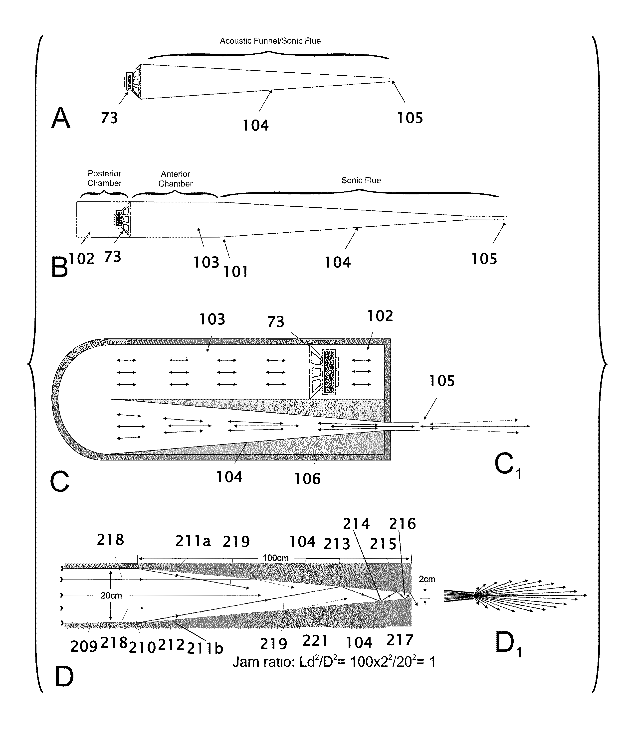
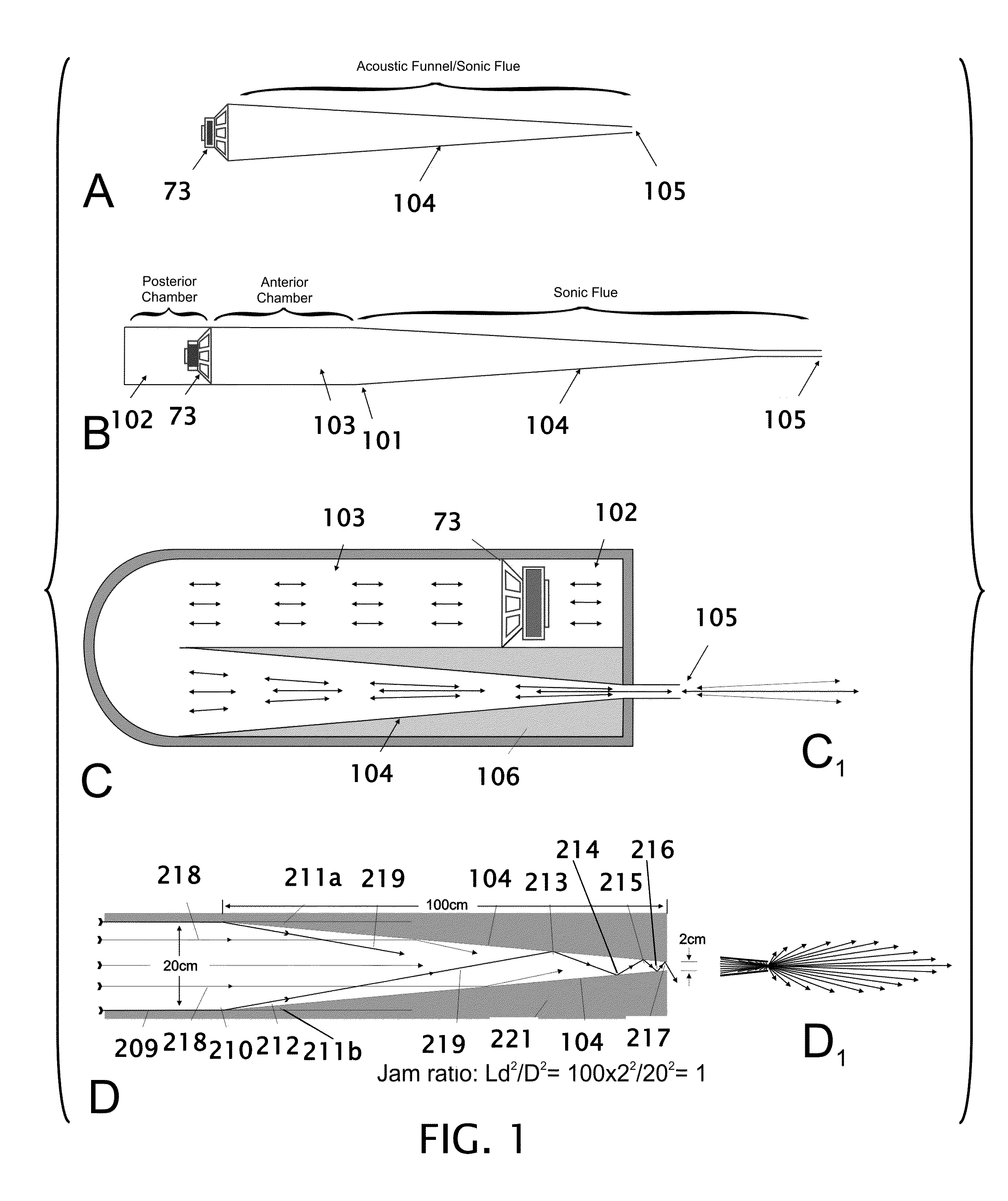
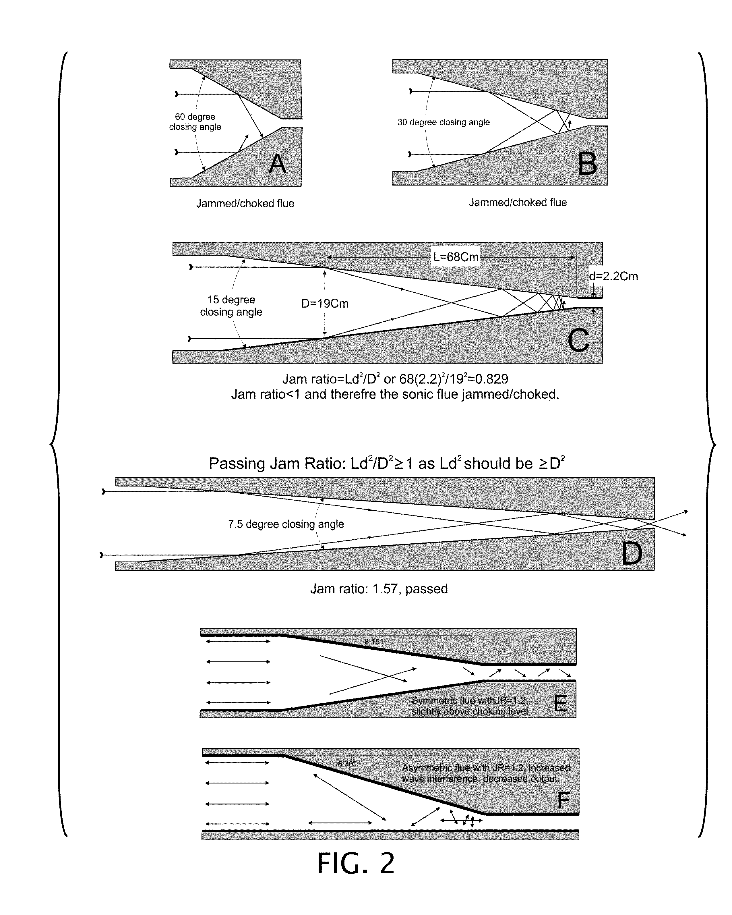
[0039]Physical design of HFOV machines gets them into a functional limitation in higher rates in a process to be called HFV choking phenomenon. Alveolar ventilation and CO2 clearance in HFV depends on Sp in patient airways. In difficult cases of CO2 retention such as RDS, these machines easily reach their highest power limit after which point the only way to improve alveolar ventilation would be to lower their oscillatory rates which is not desirable. Presently, there are no ventilator machines capable of sufficiently defying dire flow resistance of an ET tube confronting a low pulmonary compliance, a case of technological restraint contributing to high mortality and morbidity rates of certain ailments such as RDS.

[0040]Current invention describes a new method of ventilation of lungs in a safer meanwhile more effective and natural manner. It generates variable blocs of infrasonic, sonic, and ultrasonic pressure oscillations, ranging from 0-150 dB in power intensity,...


PUM


Abstract

An acoustic ventilator using feedback control is designed to generate and exert a desired mixture of pressure oscillations into a supply of gas entering a subject's airways to maintain optimal ventilation and perfusion in the lungs. According to the subject's biological specifications and real-time medical condition, computers and human interface control the vibrations in intensity and frequency along with the pressure and composition of blended gases in order to enhance oxygenation and CO2 clearance. Acoustic ventilation will cause the ventilating gases to diffuse through the subject's lungs without the aid of a separate ventilator, and with or without spontaneous breathing.

Description

CROSS REFERENCE TO RELATED APPLICATION[0001]This application claims the benefit of Provisional 61 / 748,798 filed Jan. 4, 2013 the entire contents of which is hereby expressly incorporated by reference herein.STATEMENT REGARDING FEDERALLY SPONSORED RESEARCH OR DEVELOPMENT[0002]Not ApplicableTHE NAMES OF THE PARTIES TO A JOINT RESEARCH AGREEMENT[0003]Not ApplicableINCORPORATION-BY-REFERENCE OF MATERIAL SUBMITTED ON A COMPACT DISC[0004]Not ApplicableBACKGROUND OF THE INVENTION[0005]1. Field of the Invention[0006]This invention relates to improvements in technologies and procedures involved in artificial ventilation of lungs of humans and / or animals. More particularly, the present acoustic ventilation (AV) combines sound energy from electro-acoustic transducer(s) in a multi-modal respiratory ventilation system to enhance gas exchange by improving alveolar ventilation and potentiating gas diffusion. Acoustic ventilation can maintain satisfactory gas exchange with lower mean airway pressur...

Claims


Application Information

Patent Timeline
Patent Type & Authority Applications(United States)
IPC IPC(8): A61M16/00A61M16/06A61M16/20A61M16/10A61M16/04A61M16/08
CPCA61M16/0006A61M16/209A61M16/00A61M16/0096A61M16/12A61M2016/0027A61M2016/0036A61M2205/18A61M2205/3368A61M2230/432A61M2230/435A61M16/006A61M16/107A61M16/161A61M16/205A61M16/0486A61M16/0051A61M16/024
Inventor JAM, MOHAMMAD R.
Owner JAM MOHAMMAD R
Learn More