Continuous casting apparatus for steel

a casting apparatus and steel technology, applied in the field of continuous casting apparatus for steel, can solve the problems of difficult for molten steel to flow in the regions between the long side walls and the submerged entry nozzle, and inclusions and the like, and achieve the effect of suppressing the easy trapping of bubbles by the solidified shell, uniform thickness, and reducing the risk of inclusions

Inactive Publication Date: 2014-07-10
NIPPON STEEL CORP
View PDF10 Cites 5 Cited by
  • Summary
  • Abstract
  • Description
  • Claims
  • Application Information

AI Technical Summary

Benefits of technology

[0016]According to the aspect described in the above (1), each of the long side walls has the curved portion which is convexly curved toward the electromagnetic stirring device at least at a position that faces the submerged entry nozzle, and each of the long side walls including the curved portion has a uniform thickness. Therefore, the electromagnetic force generated by the electromagnetic stirring device is uniform over the curved portion and the other parts. As a result, the flow velocity of the stirring flow becomes uniform. That is, the intensity distribution of the electromagnetic force when each of the long side walls is seen in plan view is the same in the curved portion and the parts other than the curved portion. Therefore, unlike the related art, the electromagnetic force can be prevented from becoming partially stronger at a point corresponding to the curved portion.
[0017]Therefore, the generation of a flow disturbance or a stagnant zone as in the related art can be suppressed, and easy trapping of bubbles by the solidified shell can be suppressed.
[0018]In addition, since the shortest horizontal distance between the top of the curved portion and the submerged entry nozzle is set to be 30 mm to 80 mm in a range from the position of the lower end portion of the electromagnetic stirring device to a position higher than the upper end portion of the electromagnetic stirring device by 50 mm when viewed in the height direction of the continuous casting apparatus, a smooth and uniform flow of the molten steel can be ensured even in the region between the top of the curved portion and the submerged entry nozzle.
[0019]That is, according to the knowledge newly obtained by the inventors, when the shortest horizontal distance between the top of the curved portion and the submerged entry nozzle is smaller than 30 mm, it is difficult for the molten steel to flow in the curved regions, and bubbles and the like in the molten steel are likely to be trapped by the solidified shell. In contrast, when the shortest horizontal distance exceeds 80 mm, it is difficult to ensure a uniform flow of the molten steel in the curved region, and in a region where the flow velocity of the molten steel is slow, inclusions in the molten steel are likely to be trapped by the solidified shell.
[0020]In the present invention, based on the knowledge, the shortest horizontal distance between the top of the curved portion and the submerged entry nozzle is set to 30 mm to 80 mm. Therefore, in the curved region between the top of the curved portion and the submerged entry nozzle, a smooth and uniform flow of the stirring flow of the molten steel is ensured, and bubbles in the molten steel can be prevented from being trapped by the solidified shell.
[0021]In addition, the range in the height direction in which the shortest horizontal distance between the top of the curved portion and the submerged entry nozzle is set to 30 mm to 80 mm, as such is a range from the lower end portion of the electromagnetic stirring device to a position higher than the upper end portion of the electromagnetic stirring device by 50 mm. This is because although a part of the molten steel that is directly stirred by the electromagnetic force generated by the electromagnetic stirring device is a part from the lower end portion to the upper end portion of the electromagnetic stirring device, in a practical operation, the surface of a meniscus is positioned at a position higher than the upper end portion of the electromagnetic stiffing device. In addition, typically, in the case where the surface of the meniscus is positioned at a position higher than the upper end portion of the electromagnetic stirring device, the height is at a position higher than the upper end portion of the electromagnetic stirring device by about 50 mm. Therefore, the range in the height direction in which the shortest horizontal distance between the top of the curved portion and the submerged entry nozzle is set to be 30 mm to 80 mm is from the lower end portion of the electromagnetic stirring device to the position higher than the upper end portion of the electromagnetic stirring device by 50 mm.

Problems solved by technology

Therefore, in the regions between the long side walls and the submerged entry nozzle, compared to the other regions, it is difficult for the molten steel to flow.
In addition, inclusions and the like are likely to adhere to and deposit on the periphery of the submerged entry nozzle in the casting mold.
In this case, the flow channel for the swirling flow is partially narrowed, and thus it is difficult for the molten steel to flow in the regions between the long side walls and the submerged entry nozzle.

Method used


Image

  • Continuous casting apparatus for steel
  • Continuous casting apparatus for steel
  • Continuous casting apparatus for steel

Examples


example 1

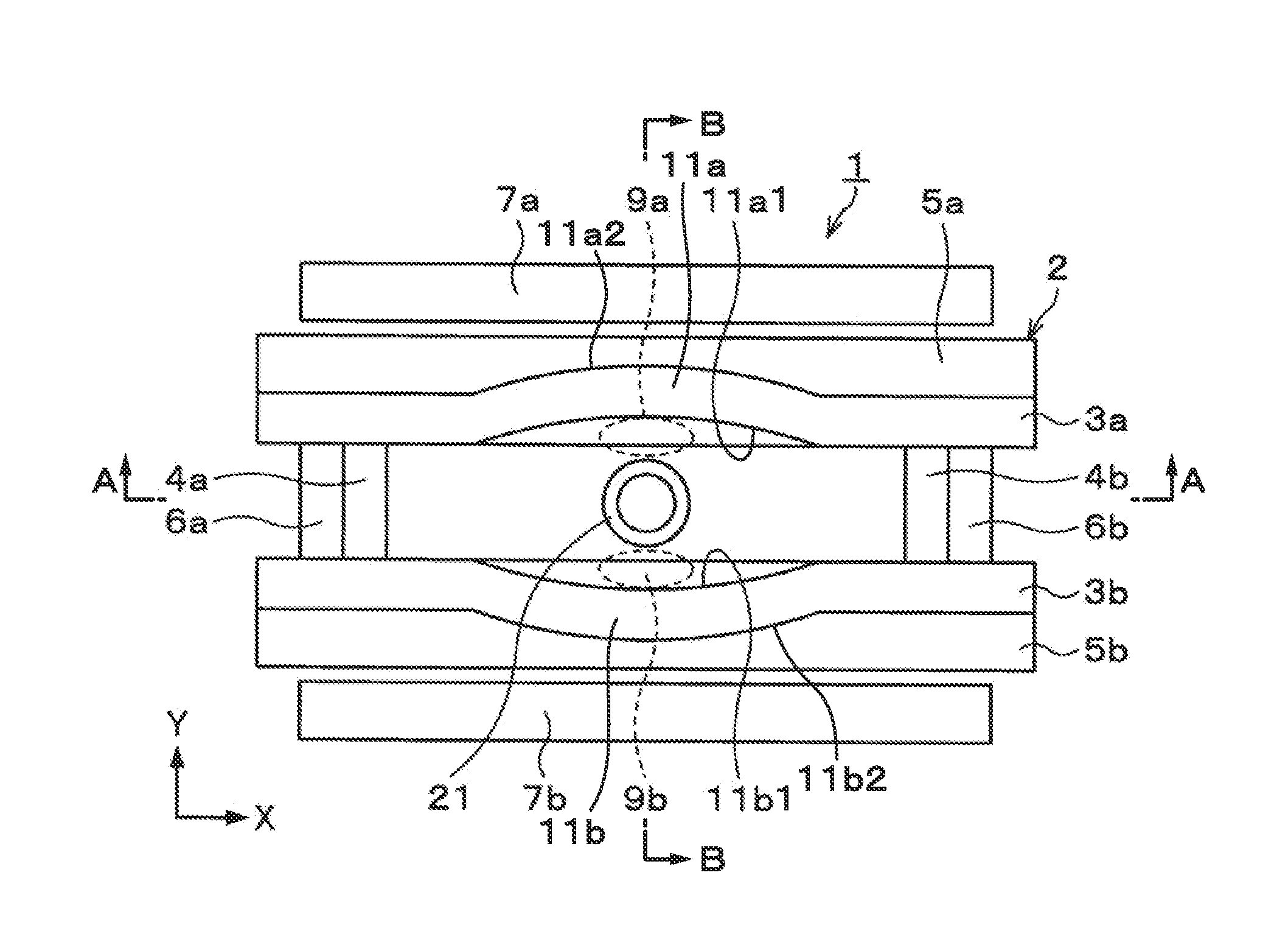
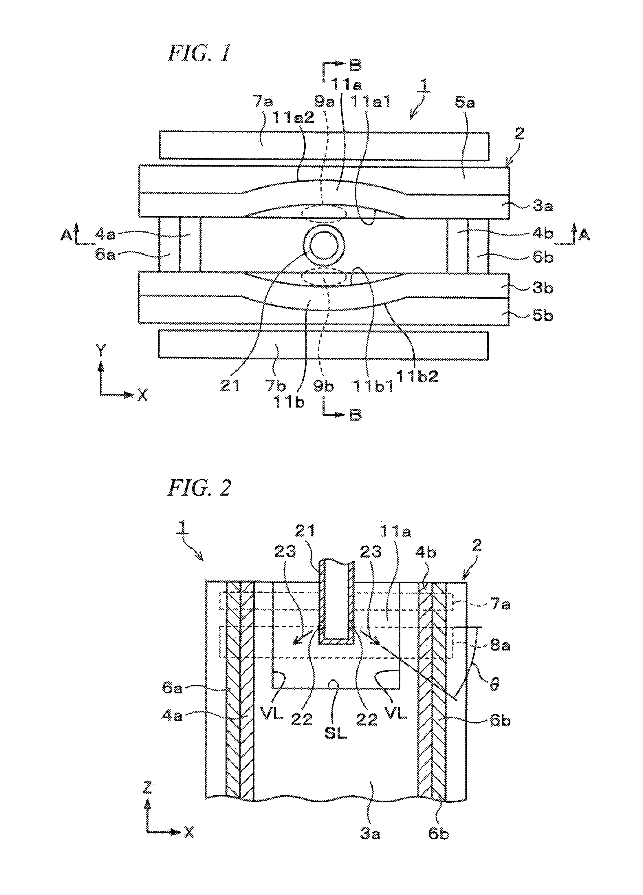
[0067]Hereinafter, an effect of removing Ar gas bubbles and inclusions included in molten steel in a case where a continuous casting apparatus for steel according to Examples of the present invention is used will be described. When the Examples were performed, the continuous casting apparatus 1 illustrated in FIGS. 1 to 3 was used as a continuous casting apparatus for steel.

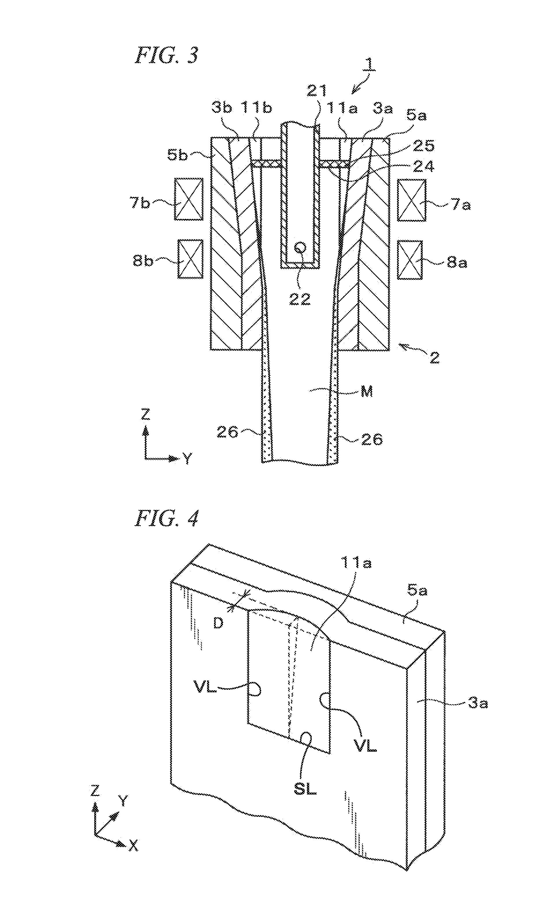
[0068]At the formation position of the meniscus 24 in the casting mold 2 having a width of 1200 mm, a height of 900 mm, and a thickness of 250 mm, the electromagnetic stirring devices 7a and 7b having a height of 200 mm and a thrust of 100 mmFe were set so that the upper end positions thereof had the same height as the position of the meniscus, and the electromagnetic brake devices 8a and 8b which were disposed to apply the maximum magnetic flux density at a position having a depth of 500 mm down from the meniscus 24 were used. In addition, the submerged entry nozzle 21 having a maximum outside diameter of 190 mm...

example 2

[0079]Next, under the same conditions as those of Example 1, the electromagnetic stirring devices 7a and 7b were also used while operating the electromagnetic brake devices 8a and 8b, and the result is shown in Table 2.

TABLE 2Distance betweenIndex ofcurved portionDepressionnumber ofand submergeddepth ofIndex ofinclusions ofentry nozzlecurved portionnumber ofcasting moldL (mm)D (mm)Ar gas bubblesparallel portion25011255113050.5140100.3150200.1160300.1170400.11.180500.11.285550.11.8

[0080]According to the result shown in Table 2, the same tendency as in the case where the electromagnetic brakes 8a and 8b were not operated was shown. That is, in a case where the distance L was 25 mm, even when the curved portions 11a and 11b having a depression depth D of 5 mm were formed, both the index of the number of Ar gas bubbles and the index of the number of inclusions were 1, and there was no change from the case where the depression depth D was 0 mm. Therefore, the number of Ar gas bubbles and...


PUM

PropertyMeasurementUnit
horizontal distanceaaaaaaaaaa
heightaaaaaaaaaa

Abstract

A continuous casting apparatus for steel includes: a casting mold for casting a molten steel with a pair of long side walls and a pair of short side walls; a submerged entry nozzle which discharges the molten steel into the casting mold; and an electromagnetic stirring device which is disposed along each external surface of each of the long side walls and stirs an upper portion of the molten steel within the casting mold. A curved portion which is convexly curved toward the electromagnetic stirring device in plan view is formed at least at a position where the curved portion faces the submerged entry nozzle on each of the long side walls, and each of the long side walls including the curved portion has a uniform thickness. The shortest horizontal distance between a top which is a most depressed position when an internal surface of the curved portion is seen in plan view and an outer peripheral surface of the submerged entry nozzle is 30 mm to 80 mm in a range from a lower end portion of the electromagnetic stirring device to a position higher than an upper end portion thereof by 50 mm when viewed along a vertical direction.

Description

TECHNICAL FIELD OF THE INVENTION[0001]The present invention relates to a continuous casting apparatus for steel, which supplies molten steel into a casting mold to manufacture a cast piece.BACKGROUND ART[0002]In continuous casting for steel, in order to improve surface properties of a cast piece, hitherto, an electromagnetic stirring device having an electromagnetic coil provided in the vicinity of the upper portion of a casting mold is used to electromagnetically stir molten steel within the casting mold.[0003]For the electromagnetic stirring, for example, the electromagnetic stirring devices are disposed along a pair of long side walls included in the casting mold. In addition, when the molten steel is discharged from a submerged entry nozzle into the casting mold, current is supplied to the electromagnetic stirring devices to apply a thrust to the upper part of the molten steel within the casting mold. The molten steel is stirred in a horizontal plane by the thrust such that a sw...

Claims


Application Information

Patent Timeline
Patent Type & Authority Applications(United States)
IPC IPC(8): B22D11/115
CPCB22D11/115B22D11/041B22D11/10
Inventor TOH, TAKEHIKONAKASHIMA, JUNJIMARUKI, YASUOYAMASAKI, NORIMASATSUNENARI, KEIJIUMETSU, KENJI
Owner NIPPON STEEL CORP
Why Eureka
Try Eureka