Method and apparatus for sheet and carton blank aligning using caster effect

a technology of caster effect and caster belt, which is applied in the direction of registering devices, thin material processing, article separation, etc., can solve the problems of inability to accurately predict the longitudinal speed of the blank, the skewed or angled blank carried on the vacuum belt, etc., and achieve the effect of accurate prediction, convenient operation and high production efficiency

Active Publication Date: 2014-07-10
TAMARACK PRODS
View PDF11 Cites 6 Cited by
  • Summary
  • Abstract
  • Description
  • Claims
  • Application Information

AI Technical Summary

Benefits of technology

[0014]An effective aligner, that also provides a firm grip and control of the blanks during alignment, has been developed using simpler, less costly components. Further, the improved aligner system can be largely adjusted by the manufacturer and requires no programming or entry of parameters by an operator and little subsequent mechanical adjustment on the part of an operator. This substantially lowers the skill level required of an operator, as well as improving the productivity of the operator and the equipment.
[0017]In one embodiment of the improved apparatus, a series of upper and lower castered or bias-angled rollers or wheels are positioned adjacent the vacuum belts. The carton blanks are gripped firmly by the upper and lower wheels. The initial angle of the wheels causes a sidewards force that urges the blank against a side guide. The side guide may be a stationary straight edge as is known, or a moving belt. The moving belt may be driven with pulleys having rotational axes either horizontal or vertical, i.e., to engage the edge or the flat side of the belt, respectively, and provides both an alignment side guide and a driving surface. The moving belt advantageously minimizes friction acting against the blank, compared to a typical stationary side guide.
[0019]As each blank is gripped by an upper and lower wheel, the blank is generally moving parallel to the vacuum belt(s). The upper wheel attempts to swing on its pivot and align itself with the direction of motion of the carton, however, that aligning tendency is resisted by the spring. The resulting lateral force pulls both the upper and lower wheels and in turn pulls the blanks towards the side guide. Once the blank is rotated and / or laterally displaced against the side guide, the blank can no longer be further displaced and it continues along the vacuum belts in alignment with the side guide. At this time, the upper and lower wheels caster, or align, themselves parallel to the side guide. At the end of the aligner section, the blank enters typical upper and lower carriers in state of the art folder / gluers and then leaves the upper and lower wheels (and also the side guide) and tends to remain in the desired orientation and position defined by the side guide. This allows subsequent operations such as folding, windowing, and gluing to be performed in the desired locations and positions on the blanks.
[0023]The castered wheel assemblies and side guide allow a firm grip of the blanks during the aligning process so the longitudinal speed of the blanks remains nearly constant. The firm grip of the wheels on the blank provide a substantial transverse force against the side guide belt. In embodiments where the guide belt is driven at the intended conveying speed, this provides a positive driving force on the carton blank. This positive drive means that the blank's speed is matched to the conveying speed and allows the blank's longitudinal position to be sensed during alignment, and its speed will closely match the guide belt speed so that the carton blank's subsequent speed and position may be accurately predicted; an important benefit that assures accuracy for subsequent timed operations such as gluing and windowing. The freedom to sense the position of the blanks during (instead of after) alignment allows a wider choice of installation position for windowing equipment such as a Tamarack Vista window applicator and may also eliminate the need to lengthen the folder / gluer to provide enough length to perform the position sensing ahead of the window film equipment—typically about two feet upstream of window application. So, the new invention has a clear advantage over prior art alignment mechanisms which require a relatively light contact with the blank so the blank can slip during the aligning process—in contrast, the new invention provides a firm grip on the carton blank during the aligning process and so that the blank's speed and position can be accurately established during aligning, instead of after aligning. While this advantage of allowing the sensing of carton position at an earlier point in the folder gluer machine is similar to the servo-driven system of Provisional Application No. 61 / 581,505, this new invention achieves it with a significantly simpler, lower cost, and easier to use apparatus.
[0024]The side aligning force can be easily limited by selecting ‘light’ springs, i.e., springs having a relatively small spring constant, or by adjustably loaded springs. This allows the instant invention to be readily used with sheets of paper which have a relatively low stiffness relative to bending. In other words, the instant invention can be adjusted so that relatively lightweight sheets or carton blanks can be aligned without buckling the sheets as they contact the side guide. The possibility of sheet buckling may also be reduced by placing the castered wheel assemblies in close proximity to the side guide.
[0025]The driven belt side guide reduces or eliminates any drag on the carton blank during the alignment process, as does to a slightly lesser extent a non-driven but idled belt or roller side guide. This reduction in drag or friction is not to be underappreciated—the fixed side guide plate of a prior art aligner can become far too hot to touch due to friction between the blanks and the fixed side guide. This reduction of friction further minimizes carton blank slippage in the longitudinal direction and again allows for more reliable position sensing. The reduced drag also reduces any tendency to buckle a corner or edge of a relatively delicate carton blank or sheet.

Problems solved by technology

However, the servo drive used in at least one embodiment is relatively expensive.
The blanks carried on the vacuum belt may be undesirably skewed or angled relative to the vacuum belts.
Both skew and lateral displacement are considered errors in position that will later cause errors in the process, such as incorrectly positioned longitudinal folds, window films, or glue lines.

Method used


Image

  • Method and apparatus for sheet and carton blank aligning using caster effect
  • Method and apparatus for sheet and carton blank aligning using caster effect
  • Method and apparatus for sheet and carton blank aligning using caster effect

Examples


Embodiment Construction

Prior Art

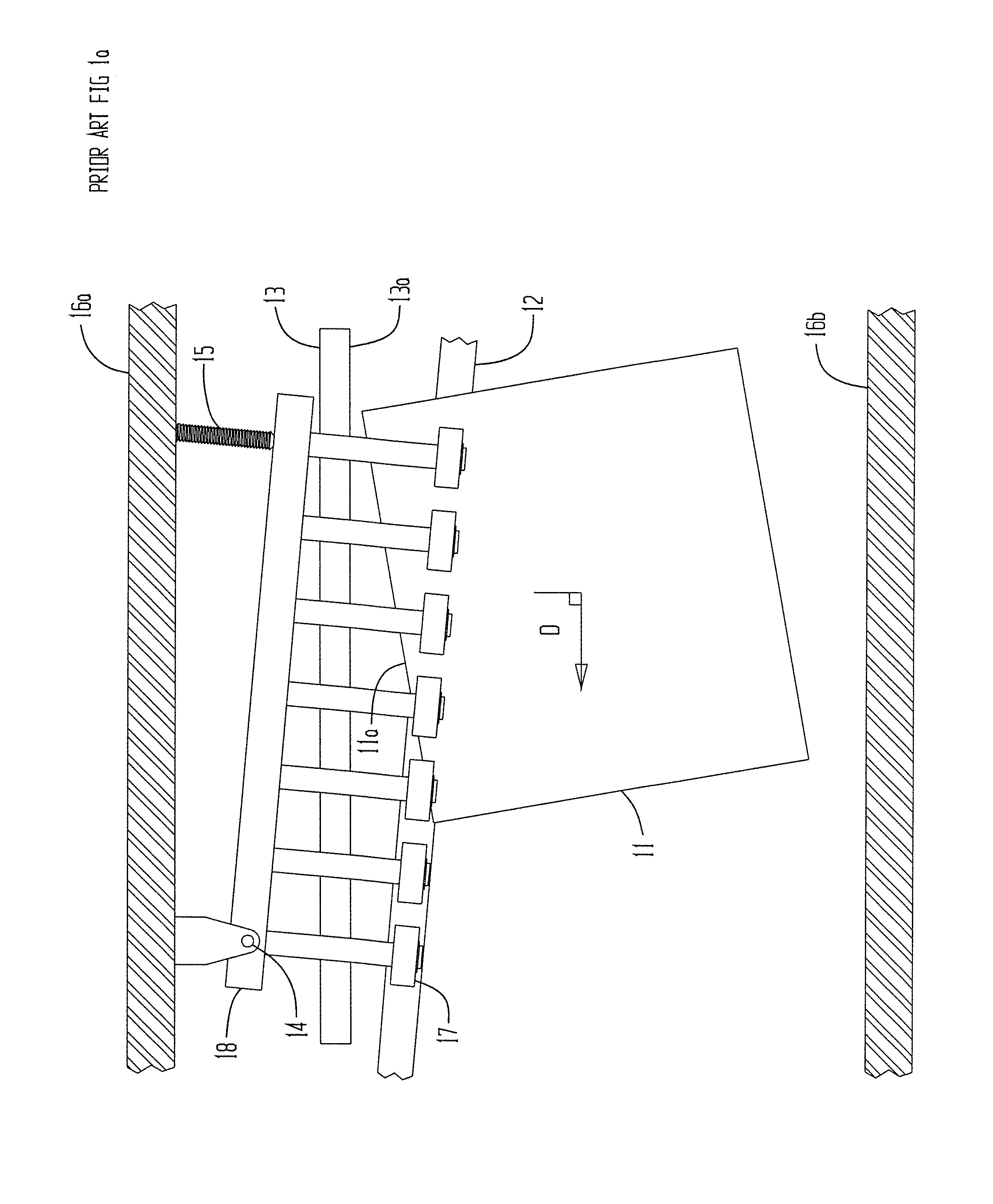
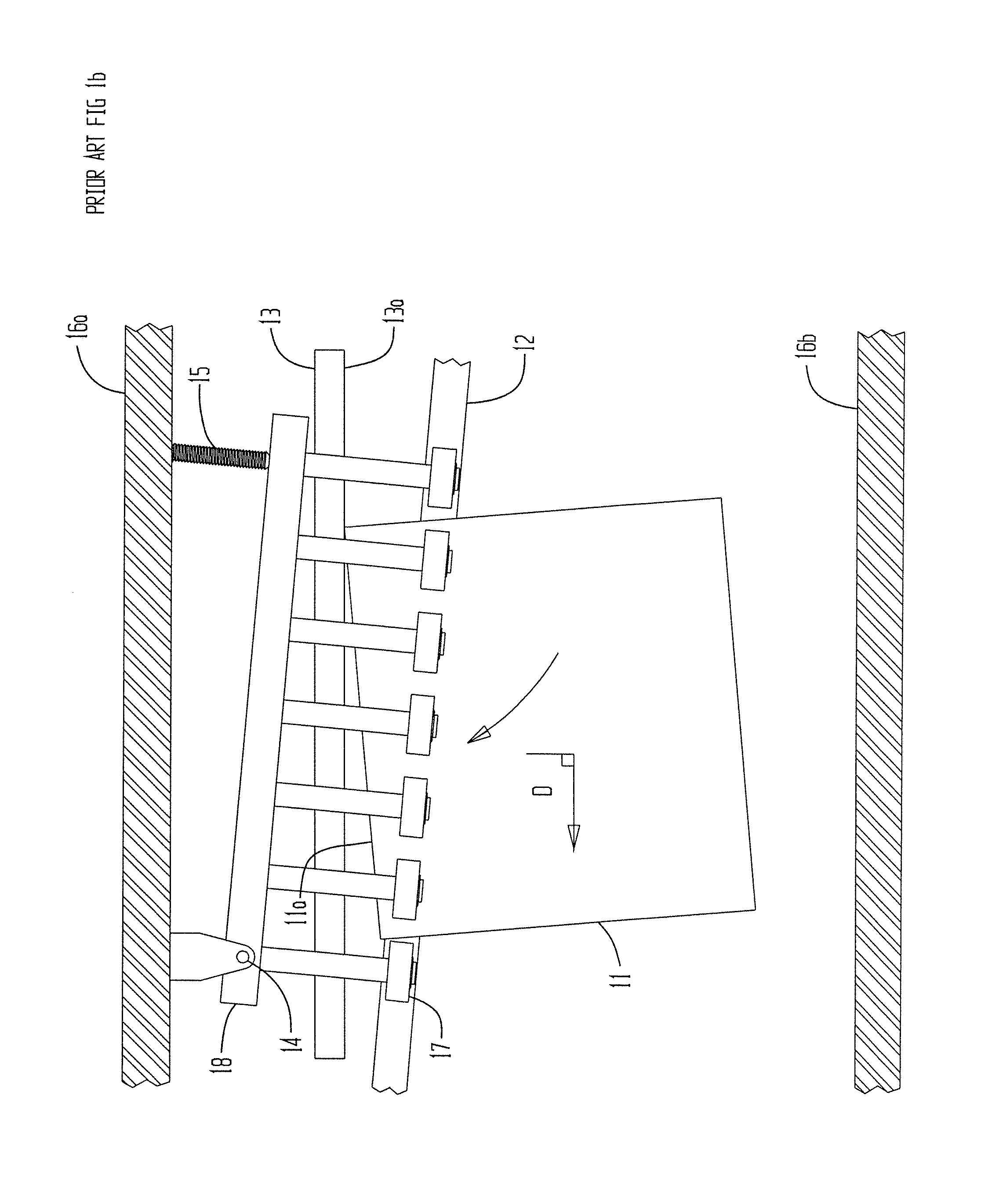
[0034]FIGS. 1a and 1b show a top view schematic of a prior art carton aligner used with prior art carton folder / gluers such as those provided by American International Machinery of Oak Creek, Wis., Bobst of Lausanne, Switzerland and Heidelberger Druckmaschinen AG of Heidelberg, Germany. Carton blank 11, shown here in a skewed orientation relative to its intended conveying direction D and is carried on driven carrier belt 12. Carrier belt 12 is typically driven by drive pulleys on a drive shaft via a motor drive system (not shown). In FIG. 1a, side edge 11a of blank is about to contact alignment bar 13. Guide bar 13 is supported by side frame 16a, by conventional means, not shown. Blank 11 is driven towards aligning surface 13a of bar 13 by a series of rollers 17 that are held on an adjustable frame 18 via pivot 14 and adjuster 15. The frame 18 is supported by side frame 16a. The rollers 17 are shown in an angled orientation relative to side frames 16a, 16b and guide bar 13 ...


PUM


Abstract

An improved apparatus and method for properly orienting and aligning flat sheets or strip material, such as in the form of folding carton blanks, on a conveying system such as used in carton folders / gluers is disclosed. A moving sheet is engaged on at least one surface by plural non-driven movable casters oriented at an angle relative to the sheet's intended direction of travel, or target direction. The casters apply a lateral force to the sheet so that a linear lateral edge of the sheet is brought into contact with an adjacent guide member aligned with the target direction, with the sheet assuming a predetermined orientation relative to the target direction. Each caster is resiliently biased such as by a spring at a predetermined angle relative to the target direction. With the sheet's lateral edge in intimate contact with the guide member, the moving sheet is in the aforementioned predetermined orientation relative to, and is displaced in, the target direction.

Description

RELATED APPLICATION[0001]The present application claims 35 USC 119(e) priority from U.S. Provisional application Ser. No. 61 / 748,953 filed Jan. 4, 2013.[0002]Portions of this disclosure are included in U.S. Provisional Application No. 61 / 581,505 filed Dec. 29, 2011, which is now U.S. patent application Ser. No. 13 / 685,801 filed on Nov. 27, 2012.BACKGROUND OF THE INVENTION[0003]In processes involving printing on sheets of material such as paper, or processing folding carton blanks, it is typically desirable that in the case of a rectangular sheet or blank that the side edges of the sheet or blank are parallel to the conveying direction and / or the leading edge is perpendicular to the conveying direction. This allows operations such as printing to be properly oriented with respect to the sheet or blank. In carton folding / gluing operations, flat carton blanks are folded along score lines and glued along a seam or at a corner or corners to provide a carton ready for subsequent uses such ...

Claims


Application Information

Patent Timeline
Patent Type & Authority Applications(United States)
IPC IPC(8): B65H9/00B65H5/22B65H5/06
CPCB65H9/002B65H5/224B65H5/068B65H9/166B65H11/005B65H2220/09B65H2404/15212B65H2404/264B65H2404/267B65H2515/30B65H2515/81B65H2701/1764B65H2220/01B65H2220/04
Inventor MACHAMER, DAVID E.
Owner TAMARACK PRODS
Why Eureka
Try Eureka