Voltage Converting LED Circuit with Switched Capacitor Network

a technology of switched capacitors and led circuits, applied in the direction of electric variable regulation, process and machine control, instruments, etc., can solve problems such as new problems, problems, and problems, and achieve the effect of quick startup tim

Active Publication Date: 2014-07-10
FERRARIO BRUNO +2
View PDF5 Cites 15 Cited by
  • Summary
  • Abstract
  • Description
  • Claims
  • Application Information

AI Technical Summary

Benefits of technology

[0019]When the load is turned ON for the next PWM cycle, the reconnection of the capacitor to the network allows the error amplifier to be closely biased to its “final state”, resulting a much quicker startup time.

Problems solved by technology

The downside of this method is that altering the current through an LED skews the color spectrum that the LED produces, making the expected white color warmer or cooler.
However, manufacturing variations invariably result in imperfect parts.
Problems start to arise when the voltage produced by the power supply inadequately matches the sum of the voltages required by the current sinks and the strings of LED's—the supplied voltage might be too high or too low.
This introduction brings with it a new problem.
This solution does not work well when the LED strings are pulsed ON and OFF at high PWM frequencies.
The higher the PWM frequency, the less acceptable these transients become.

Method used


Image

  • Voltage Converting LED Circuit with Switched Capacitor Network
  • Voltage Converting LED Circuit with Switched Capacitor Network
  • Voltage Converting LED Circuit with Switched Capacitor Network

Examples


Embodiment Construction

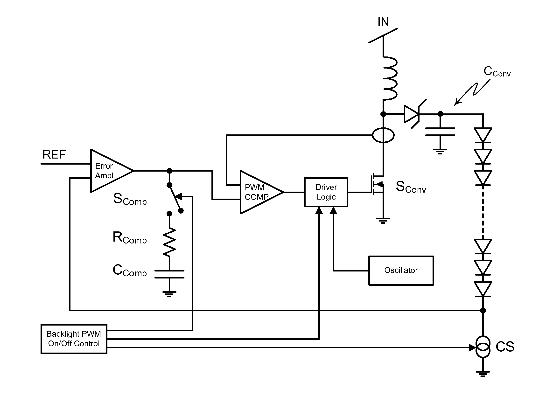
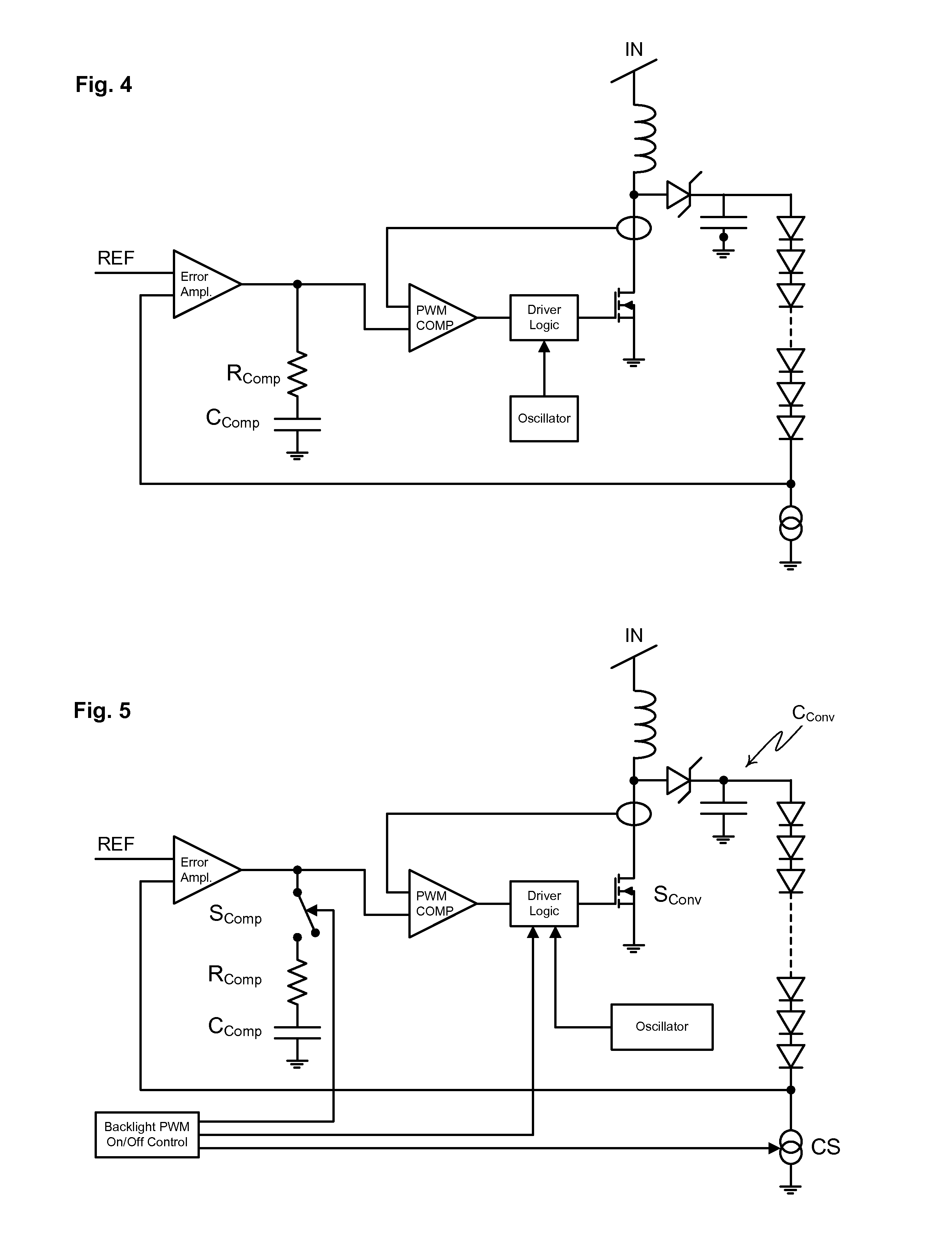
[0030]FIG. 5 shows a circuit that is a preferred embodiment of the invention. This circuit could be found inside a one-LED-string television together with a power supply that produces a voltage lower than is required to operate the string of LED's. In this particular embodiment, the voltage from the power supply is stepped up in order to operate the string of LED's. The circuit comprises five general parts: the boost converter, the LED channel that comprises the LED string and the current sink, the error amplifier, and the switched capacitor network. Central to this embodiment of the invention is the backlight PWM control, but as is the case with the power supply, the exact control mechanism is external to the claimed invention.

[0031]The boost converter comprises the inductor, the switch marked SConv, the capacitor marked CConv, the diode, the driver logic module, the oscillator, the current measuring device, and the PWM comparator. All of these units function together, converting t...


PUM


Abstract

A Voltage Converting LED Circuit with Switched Capacitor Network contains a 2-way MOSFET switch that connects a capacitor network to the output of an error amplifier, thereby enabling the error amplifier to resume operation quickly after the off-time segment of a PWM cycle. The switch is controlled synchronously with current sinks controlling brightness and color levels. In a preferred embodiment, multiple serially connected strings of LED's can be controlled simultaneously via one switch.

Description

RELATED APPLICATIONS[0001]This application is related to the subject matter of a concurrently filed application entitled “Multiple Chip Voltage Feedback Technique for Driving LED's.” The disclosure of the concurrently filed application is incorporated in this application by reference.BACKGROUND OF THE INVENTION[0002]Current LCD screens with white LED backlight technology use a variety of configurations of the LED backlights. In these devices, the color of the picture is generated by opening and closing the LCD's; the brightness of the picture is provided from the LED backlight.[0003]In these screens, there is more than one method of controlling the brightness of these screens that a human observer perceives. For example, some devices control the current that flows through the LED's, as more current through a LED tends to make the LED brighter. The downside of this method is that altering the current through an LED skews the color spectrum that the LED produces, making the expected w...

Claims


Application Information

Patent Timeline
Patent Type & Authority Applications(United States)
IPC IPC(8): H02M3/156H05B33/08H05B44/00
CPCH05B33/0815H02M3/156H02M1/36H05B45/20H05B45/38H05B45/375
Inventor FERRARIO, BRUNOSIEN, YUN TUNG
Owner FERRARIO BRUNO
Why Eureka
Try Eureka