Technique for reducing power consumed by electric equipment
- Summary
- Abstract
- Description
- Claims
- Application Information
AI Technical Summary
Benefits of technology
Problems solved by technology
Method used
Image

Examples
first embodiment
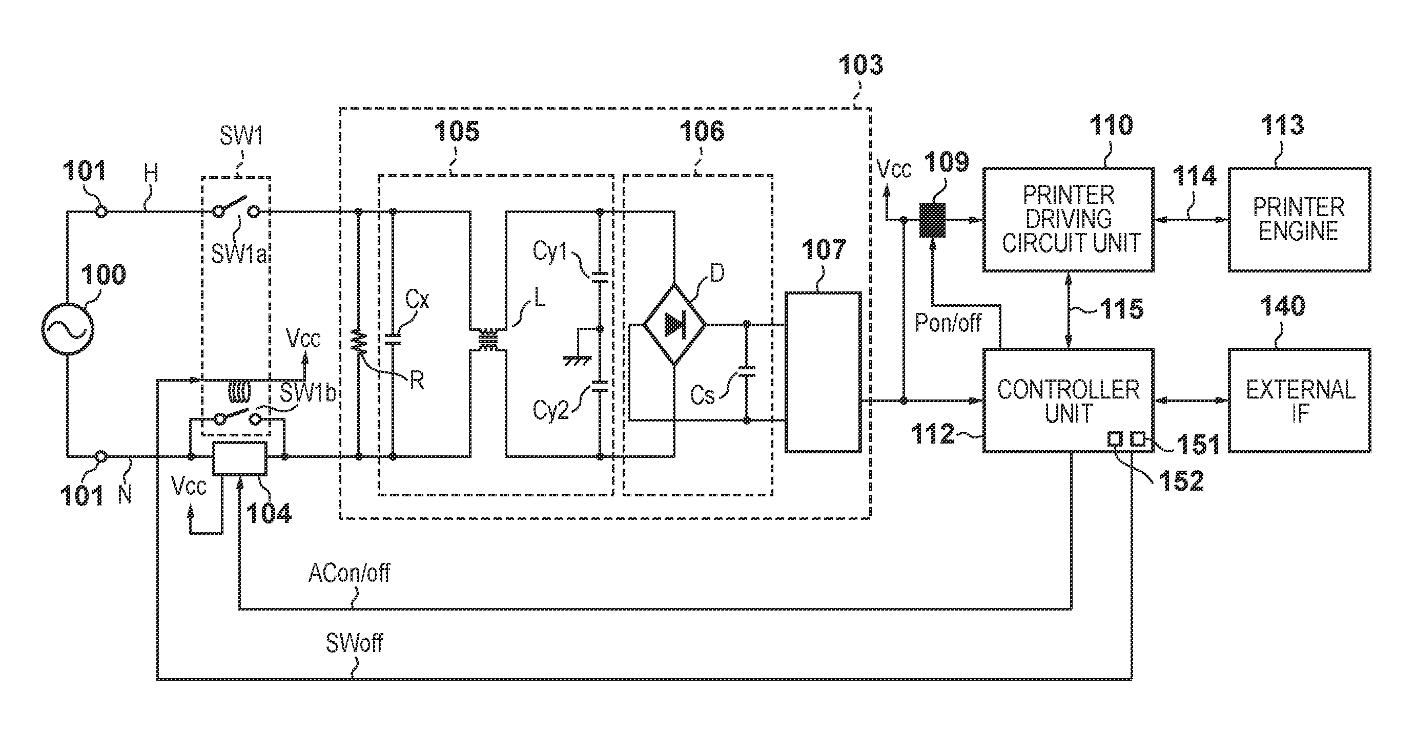
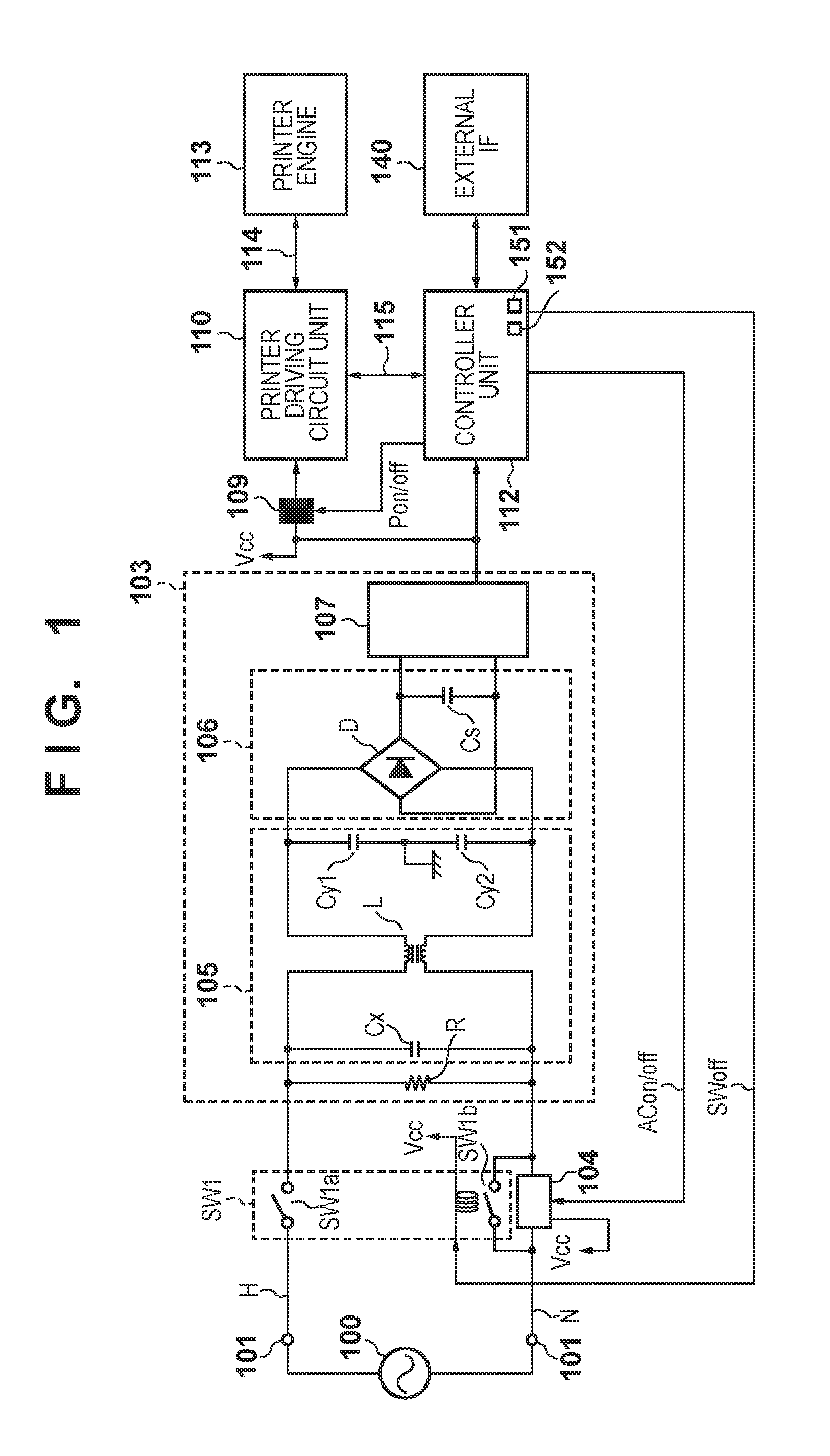
[0023]Blocks involved in power supply control of an image forming apparatus will first be described using FIG. 1. An AC power plug 101 of the image forming apparatus is connected to a commercial AC power supply 100. Two AC power supply lines from the AC power plug 101, namely a hot line H and a neutral line N, are connected to a DC power supply 103. A main power supply switch SW1 and an AC cutting circuit 104 are inserted between the AC power plug 101 and the DC power supply 103. The main power supply switch SW1 and the AC cutting circuit 104 can cut an AC current input from the commercial AC power supply 100. The DC power supply 103 generates a DC voltage Vcc by rectifying and smoothing the input AC voltage. The DC voltage Vcc is supplied to a controller unit 112 that controls operations of the image forming apparatus. The DC voltage Vcc is a voltage suited to integrated circuits used for control, such as 3.3 V, for example. Although not illustrated in the drawings, the DC power su...
second embodiment
[0068]A second embodiment will be described using FIG. 4. In the present embodiment, the aforementioned second switch contact SW1b is configured of a single switch contact of a main power supply switch SW2, and an AC cutting relay RL.
[0069]In the present embodiment, of the two contacts in the main power supply switch SW2, the AC cutting circuit 104 is connected serially to the contact that is itself connected serially to the neutral line N. The AC cutting circuit 104 is connected in parallel to the AC cutting relay RL. In other words, the AC cutting relay RL is connected serially to the contact that is itself connected serially to the neutral line N. The AC cutting relay RL is switched on through mechanically linked operations when the operator switches the main power supply switch SW2 on. Meanwhile, the AC cutting relay RL is switched off when the switch-off signal SWoff is supplied. As a result, the second embodiment operates in the same manner as the first embodiment. Accordingly...
third embodiment
[0070]A third embodiment will be described using FIG. 5. In the third embodiment, the second switch contact SW1b described in the first embodiment is configured of a second switch contact SW3b and a bistable relay (latching relay) RLb. A further feature of the present embodiment is that a circuit element that detects whether a main power supply switch SW3 is on or off is provided, so that the bistable relay RLb is turned on with certainty when the main power supply switch SW3 is off.
[0071]As shown in FIG. 5, the main power supply switch SW3 includes three contacts. A first switch contact SW3a and the second switch contact SW3b are contacts that cut the hot line H and the neutral line N, which are power supply lines from the commercial AC power supply 100. The first switch contact SW3a is connected serially to the hot line H. The second switch contact SW3b is connected serially to the neutral line N. The second switch contact SW3b is also connected serially to the AC cutting circuit ...
PUM
 Abstract
Description
Claims
Application Information
 - R&D Engineer
- R&D Manager
- IP Professional
- Industry Leading Data Capabilities
- Powerful AI technology
- Patent DNA Extraction
Browse by: Latest US Patents, China's latest patents, Technical Efficacy Thesaurus, Application Domain, Technology Topic.
© 2024 PatSnap. All rights reserved.Legal|Privacy policy|Modern Slavery Act Transparency Statement|Sitemap