Fiber optic connector assemblies having windowed optical fibers and methods thereof

a technology of fiber optic connectors and fiber optic connectors, which is applied in the direction of instruments, mechanical equipment, transportation and packaging, etc., can solve the problems of fatigue and damage of optical fibers, optical misalignment between optical fibers and optical components within the connector, and the difficulty of ggp fibers to be difficult to demark with strong retention in the connector body, so as to reduce the stress on optical fibers

Active Publication Date: 2014-07-10
CORNING OPTICAL COMM LLC
View PDF6 Cites 17 Cited by
  • Summary
  • Abstract
  • Description
  • Claims
  • Application Information

AI Technical Summary

Benefits of technology

[0007]Embodiments of the present disclosure relate to fiber optic connectors of optical cable assemblies, such as active optical cable assemblies that convert optical signals into electrical signals, and electrical signals into optical signals. The embodiments described herein reduce stress on the optical fibers and optical components within a connector housing of the fiber optic connector by use of windowed portions formed in the optical fibers where a portion of an inner glass region is exposed. Glass, glass polymer (GGP) fibers are a type of optical fiber comprising a glass core surrounded by a glass cladding. One or more polymer layers, such as a polymer coating, is disposed about the inner glass region defined by the glass core and the glass cladding. However, such GGP fibers may be difficult to demark with strong retention in a connector body due to the tendency of the inner glass region to pull through the polymer layers under tension.
[0008]In some embodiments described herein, one or more optical fibers are disposed in a demarcation body, such as a connector housing or body, such that at least a portion of the windowed portions are aligned at a demarcation element of the demarcation body. An adhesive is bonded directly to the inner glass region of the optical fibers for adhering the optical fibers to the demarcation body. Because the inner glass regions of the optical fibers are bonded to the demarcation body, the inner glass region does not pull through the one or more polymer layers under tensile stress, thereby increasing the strength of retention. In other words, the adhesive is bonded to the inner glass region of the optical fiber so that the glass of the optical fiber can not slip relative to the coating under tensile stress or the like.

Problems solved by technology

Stresses on optical fibers within the fiber optic cable assembly may cause fatigue and damage to the optical fibers, as well as other components, within the fiber optic connector of the fiber optic cable assembly.
Such stresses may also cause optical misalignment between the optical fibers and optical components within the connector, such as light emitting and receiving active components.
However, such GGP fibers may be difficult to demark with strong retention in a connector body due to the tendency of the inner glass region to pull through the polymer layers under tension.

Method used


Image

  • Fiber optic connector assemblies having windowed optical fibers and methods thereof
  • Fiber optic connector assemblies having windowed optical fibers and methods thereof
  • Fiber optic connector assemblies having windowed optical fibers and methods thereof

Examples


Embodiment Construction

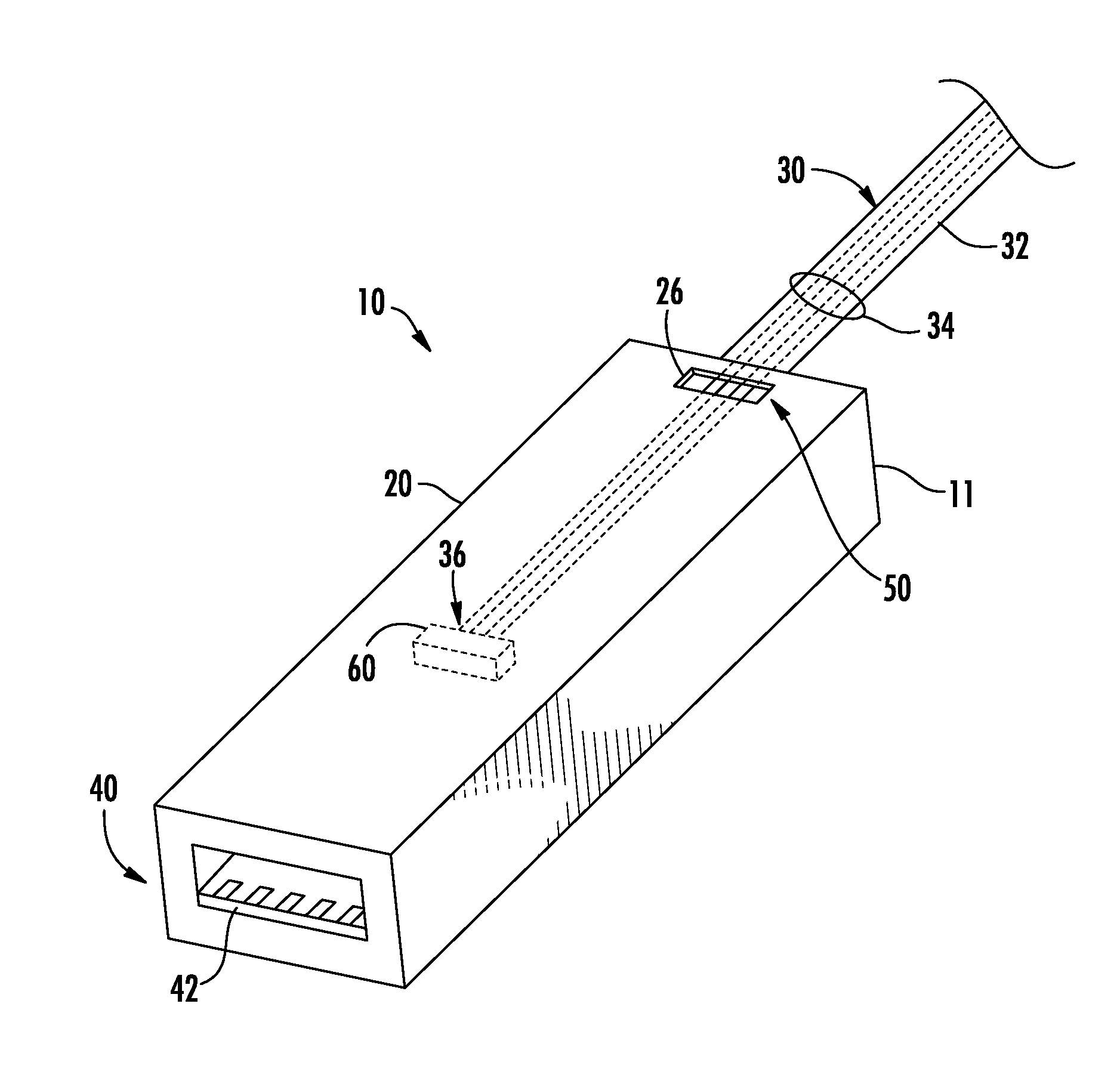
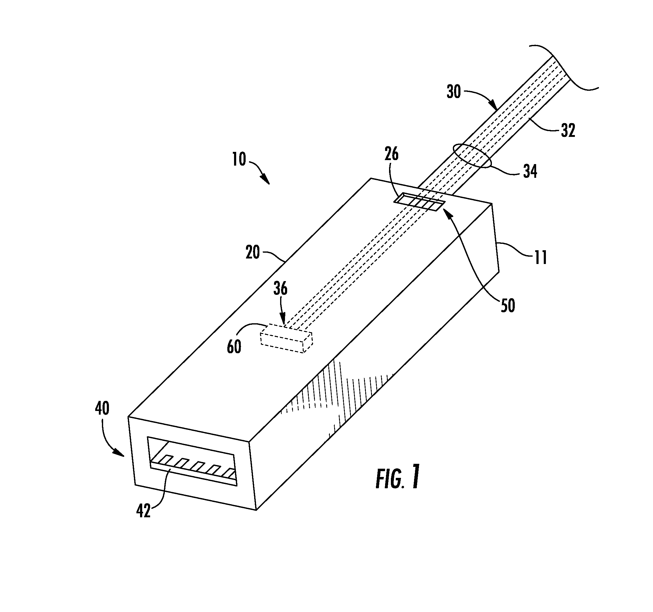
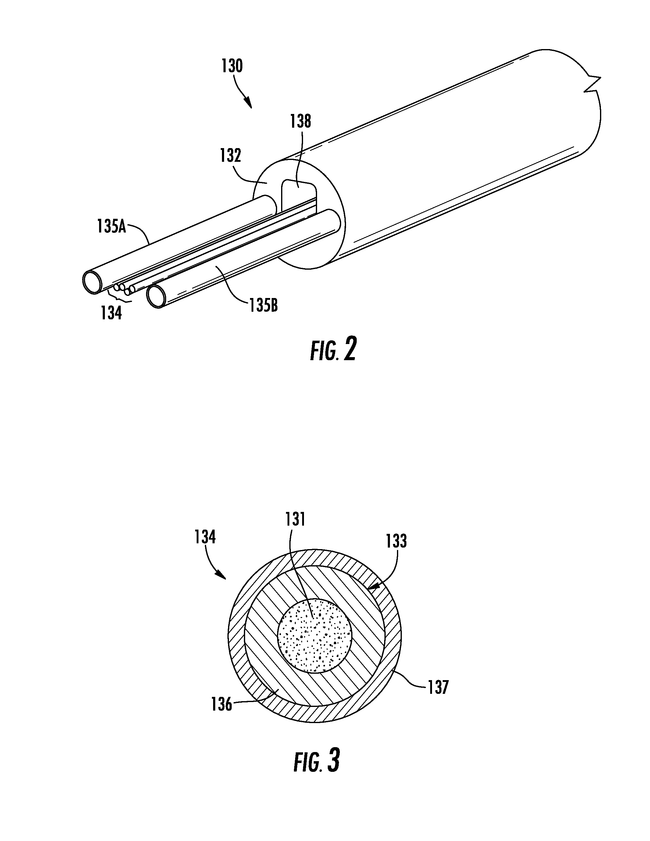
[0029]Some aspects of the present disclosure are directed to fiber optic connectors of optical cable assemblies. As an example and not a limitation, embodiments described herein may be incorporated into active optical cables that convert electrical signals into optical signals for optical transmission over the optical cable, and optical signals into electrical signals for transmission to a coupled electronic device. In fiber optic connector applications, the connector housing acts as a demarcation body to which the plurality of optical fibers within an optical cable are secured. Embodiments described herein may provide increased mechanical robustness of fiber optic connectors by use of one or more windowed regions in each of the optical fibers that are coupled to the demarcation body. The inner glass region of the optical fibers is exposed at the windowed region such that the adhesive that secures the optical fibers to the demarcation body adheres to the glass region of the optical ...


PUM

PropertyMeasurementUnit
lengthaaaaaaaaaa
lengthsaaaaaaaaaa
diameteraaaaaaaaaa

Abstract

Fiber optic connector assemblies and method for assembling the same are disclosed. In one embodiment, a fiber optic connector assembly includes an optical fiber having an inner glass region, a polymer layer surrounding the inner glass region, and a windowed portion, wherein the inner glass region is exposed at the windowed portion. The fiber optic connector assembly further includes a connector body having a demarcation region at a first end, wherein the optical fiber is disposed within the connector body such that at least a portion of the windowed portion is positioned in the demarcation region, and the optical fiber is adhered to the connector body at the windowed portion. In another embodiment, the demarcation region includes an opening in the outer jacket that exposes the at least a portion of the windowed portion of the plurality of optical fibers and the optical fibers are adhered to a portion of the cable.

Description

BACKGROUND[0001]1. Field[0002]The present disclosure generally relates to fiber optic connector assemblies for optical fiber cables and, more particularly, fiber optic connector assemblies having optical fibers with windowed portions exposing inner glass regions that are bonded to a demarcation body.[0003]2. Technical Background[0004]Fiber optic cables are an attractive alternative to bulky traditional conductor cables, especially as data rates increase. As the use of fiber optics migrates into numerous consumer electronics applications, such as connecting computer peripherals by the use of fiber optic cable assemblies, there will be a consumer driven expectation for cables having improved performance, compatibility with future communication protocols, and a broad range of use. For example, it is likely that consumer demand will be for an active fiber optic cable that is compatible with protocols such as universal serial bus specification version 3.0 (USB 3.0), Thunderboltâ„¢, or the ...

Claims


Application Information

Patent Timeline
Patent Type & Authority Applications(United States)
IPC IPC(8): G02B6/36
CPCG02B6/36G02B6/3887G02B6/245Y10T156/1043G02B6/4214G02B6/4284G02B6/3889
Inventor ISENHOUR, MICAH COLENKNECHT, DENNIS MICHAELLUTHER, JAMES PHILLIPROBERTS, REGINALD
Owner CORNING OPTICAL COMM LLC
Why Eureka
Try Eureka