
Landscaping tool system including tamp, scuffle hoe, and rake

a tool system and tool technology, applied in the field of ball field equipment, can solve the problems of tamps having a tendency to break, unable to provide an added shaft between the plate and the pole, and affecting the appearance of the landscape,

Inactive Publication Date: 2014-07-10
BULLDOG FIELD EQUIP
View PDF19 Cites 2 Cited by
  • Summary
  • Abstract
  • Description
  • Claims
  • Application Information

AI Technical Summary

Benefits of technology

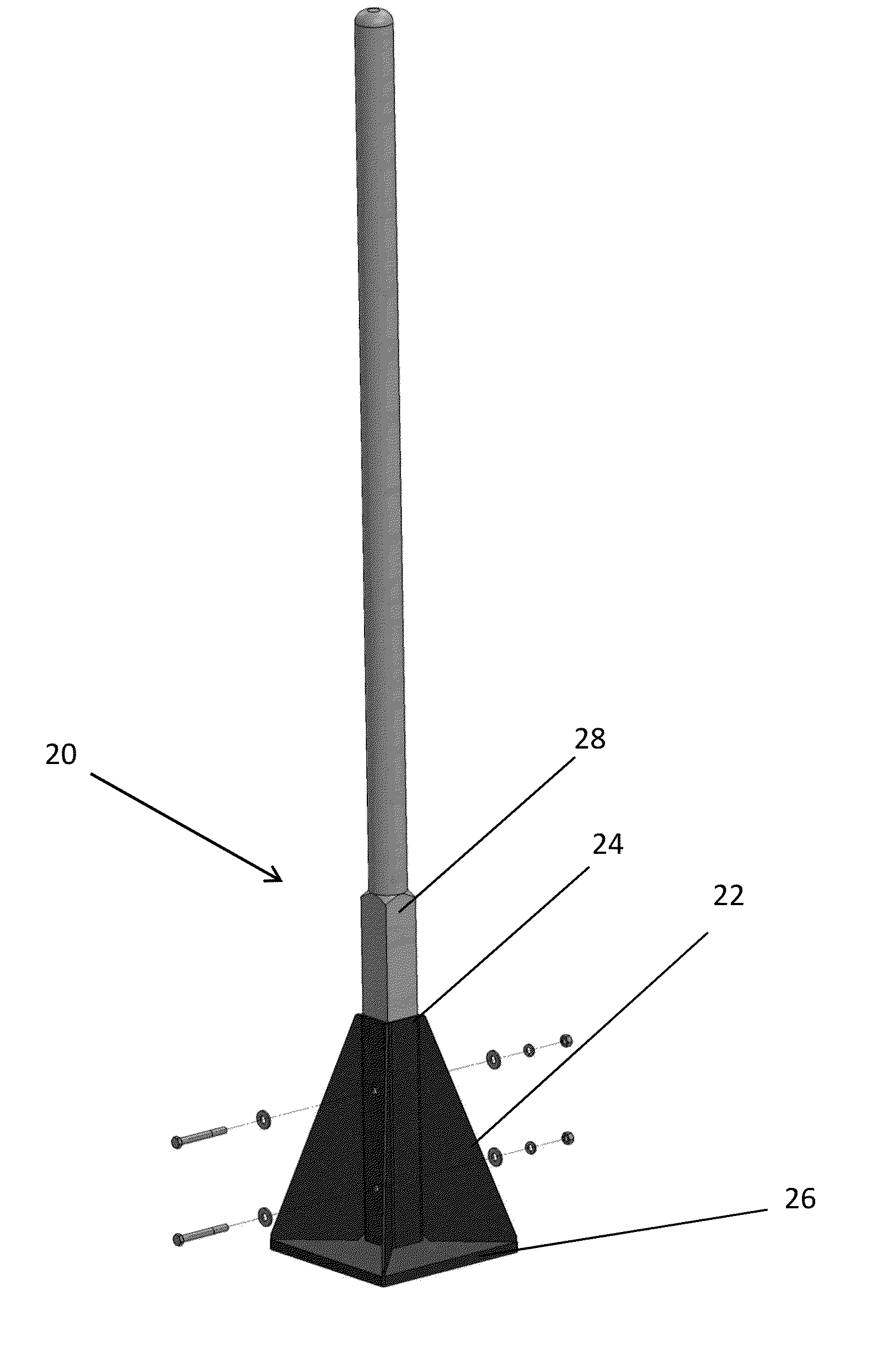
The invention provides an improved tamp with a reinforced plate and shaft that can withstand repeated striking on hard surfaces without breaking. The shaft is taller than the plate, and support fins are secured between them. This design strengthens the area most likely to break and makes the tool more durable. Optionally reinforcing the shaft further up the pole and / or reinforcing the plate and shaft with support fins provides an even stronger tamp. The support fins can be triangular or crescent-shaped and are positioned to prevent bending between the plate and shaft or pole and plate. The fins provide flexibility and allow for a small amount of bending during use.

Problems solved by technology

Some tamps provide a tamp plate connected directly to and perpendicular to the tamp pole with little or no added support, and do not provide an added shaft between where the plate and pole meet.
Since this connection is not well supported this area becomes vulnerable.
Over time these tamps have a tendency to break where the plate joins the pole as the tamp is constantly applied to uneven clay and dirt surfaces.
Other designs employ a shaft to receive the pole, however, the height of the shaft relative to the length of the plate sides is too short to address this problem of breakage.
In such designs, it is the handle (otherwise referred to as the tool pole or tamp pole) that is susceptible to breaking where the handle meets the shaft.

Method used


Image

  • Landscaping tool system including tamp, scuffle hoe, and rake
  • Landscaping tool system including tamp, scuffle hoe, and rake
  • Landscaping tool system including tamp, scuffle hoe, and rake

Examples


Embodiment Construction

[0050]Reference will now be made in detail to various exemplary embodiments of the invention. It is to be understood that the following discussion of exemplary embodiments is not intended as a limitation on the invention. Rather, the following discussion is provided to give the reader a more detailed understanding of certain aspects and features of the invention.

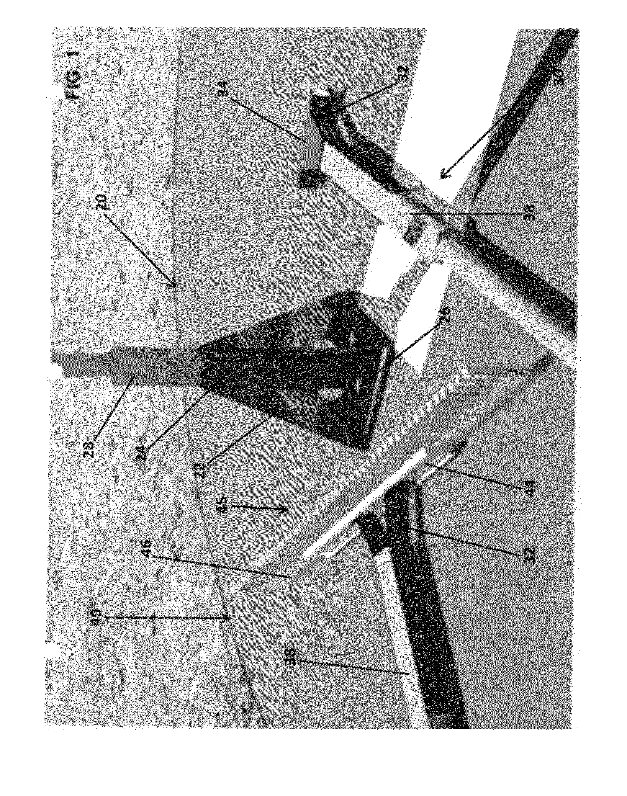
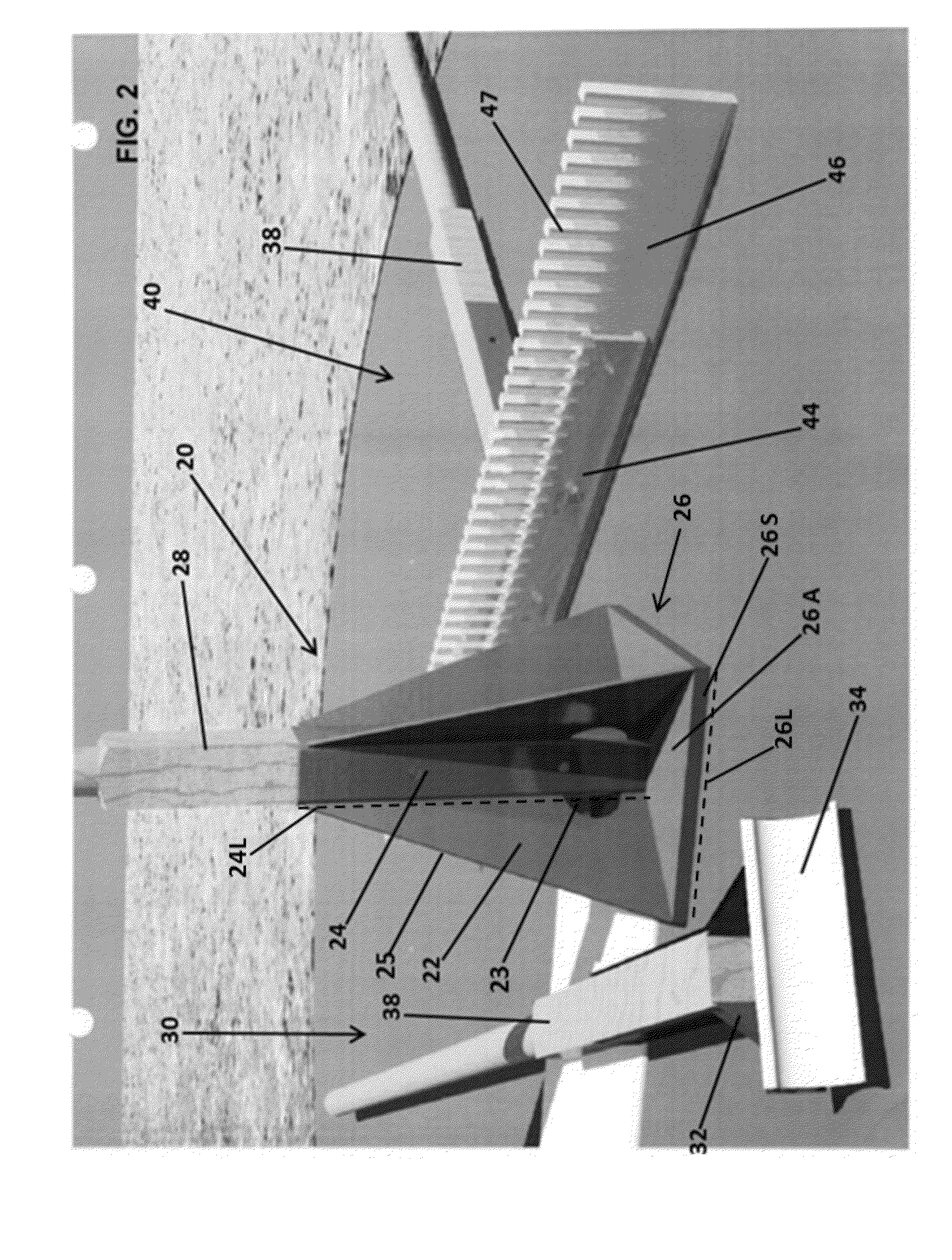
[0051]In accordance with embodiments of the present invention, provided is a tamp comprising a shaft perpendicularly connected to a base plate, where the shaft and plate are further secured together by fins disposed along substantially the entire length of the plate and / or the height of the shaft. The height of the shaft can be greater than or equal to the length of one side of the plate. Further, the tamp can be connected to a pole or handle to provide leverage to a user when using the tamp. Such tamps provide a durable construction with improved performance characteristics over that of existing designs.

[0052]FIGS. 1-5 illu...


PUM


Abstract

Methods, systems and tools used for landscaping are described. In particular, a system is provided for maintaining the landscape features of a baseball or softball field. The system can realize several different tools from interchangeable components without compromising the structural integrity and tool performance necessary to accomplish the job. Embodiments of tools include an improved tamp comprising a metallic plate with a first surface and a second surface disposed parallel to the first surface, wherein the second surface is configured such that the surface can compact particulate material into a more compressed state when pounded against it; and an open columnar member, for receiving a handle, disposed on and fixed to the first surface of the metallic plate; wherein the metallic plate has sides of equal length forming a square outline and the open columnar member has a height that is greater than the length of the metallic plate sides.

Description

CROSS-REFERENCE TO RELATED APPLICATIONS[0001]The present application relies on the disclosure of and claims priority to and the benefit of the filing dates of U.S. Provisional Application No. 61 / 750,059 and U.S. Provisional Application No. 61 / 750,089, both filed on Jan. 8, 2013, the disclosures of which are hereby incorporated by reference herein in their entireties.BACKGROUND OF THE INVENTION[0002]1. Field of the Invention[0003]The present invention relates to the field of ball field equipment. More specifically, embodiments of the present invention relate to methods, systems and tools for landscaping. Embodiments of the invention provide manual dirt tamps for compacting soil, clay, or other particular matter, which tamps are useful for baseball or softball field maintenance. Embodiments of the invention also include a scuffle hoe, rake, and interchangeable tool system comprising them. The tools and systems are especially helpful for maintaining a baseball or softball field.[0004]2...

Claims


Application Information

Patent Timeline
IPC IPC(8): E02D3/046
CPCE02D3/046
Inventor KROPFF, CHADCOLLINS, DAVID ERICKROPFF, CATHERINE
Owner BULLDOG FIELD EQUIP
Learn More