Air engine with rotatable intake-exhaust mechanism

a technology of air engine and intake-exhaust valve, which is applied in the direction of machines/engines, oscillatory slide valves, servomotors, etc., can solve the problem that the efficiency of air engine cannot be effectively enhanced, and achieve the effect of increasing the working efficiency of air engin

Inactive Publication Date: 2014-07-17
NATIONAL TSING HUA UNIVERSITY
View PDF17 Cites 2 Cited by
  • Summary
  • Abstract
  • Description
  • Claims
  • Application Information

AI Technical Summary

Benefits of technology

[0010]It is therefore an object of the invention to provide an air engine with a rotatable intake-exhaust mechanism for achieving the effect of instantaneously opening and closing valves and for effectively increasing the working efficiency of the air engine.
[0012]With the air engine of the invention, controlling the instantaneous open and close operations of the valves can provide more sufficient intake and exhaust for the engine to increase the efficiency. Because no cam is needed, no complicated mechanism has to be disposed, and no hysteresis phenomenon is caused upon the power transmission of the cam (especially at the high rotating speed). Because no fuel is provided and burned, no contaminated exhaust gas is generated, and no spark plug or high-pressure nozzle is needed to perform the ignition operation. Therefore, the air engine of the invention has the relatively high applicability and economy after the intake and exhaust strokes are improved.

Problems solved by technology

If the internal combustion engine is modified into the air engine, the efficiency of the air engine cannot be effectively enhanced due to the gradually opening and closing operations of the valves.

Method used


Image

  • Air engine with rotatable intake-exhaust mechanism
  • Air engine with rotatable intake-exhaust mechanism
  • Air engine with rotatable intake-exhaust mechanism

Examples


first embodiment

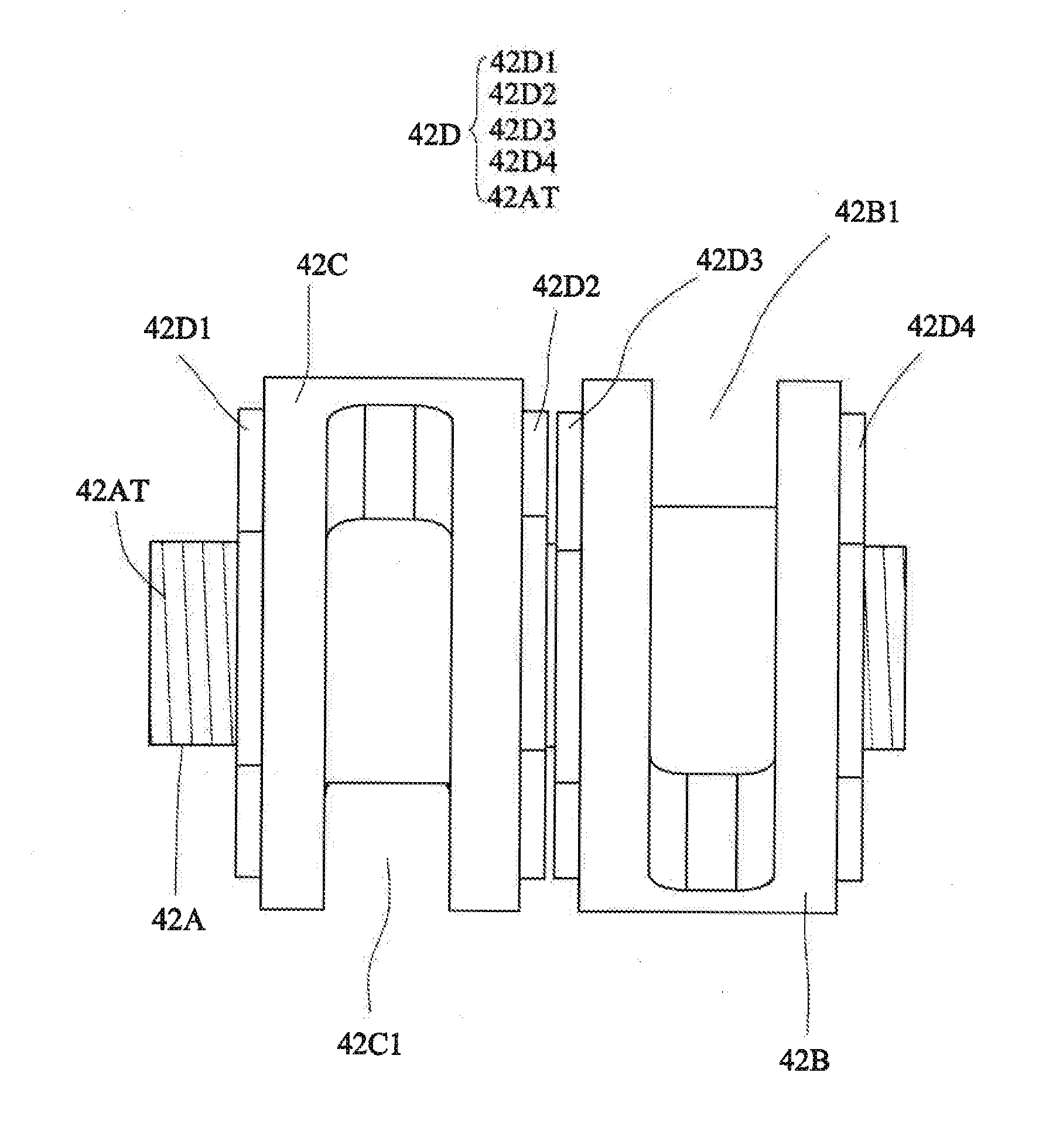
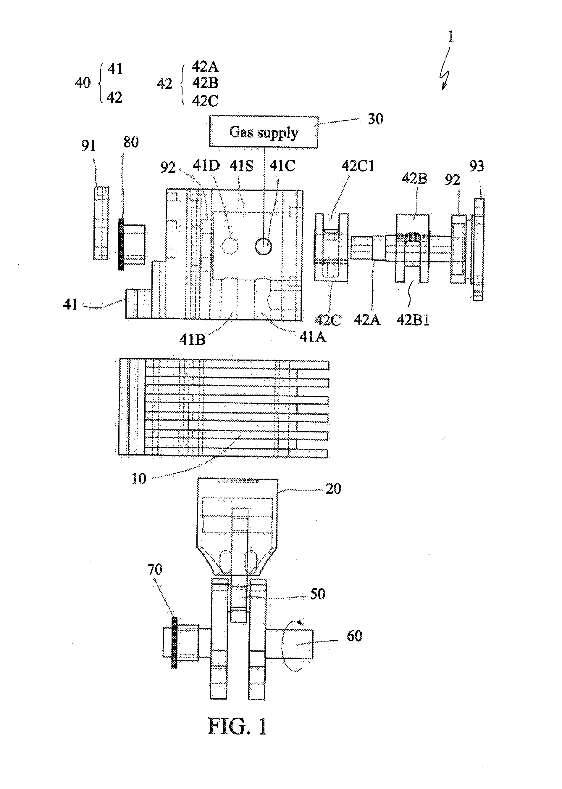
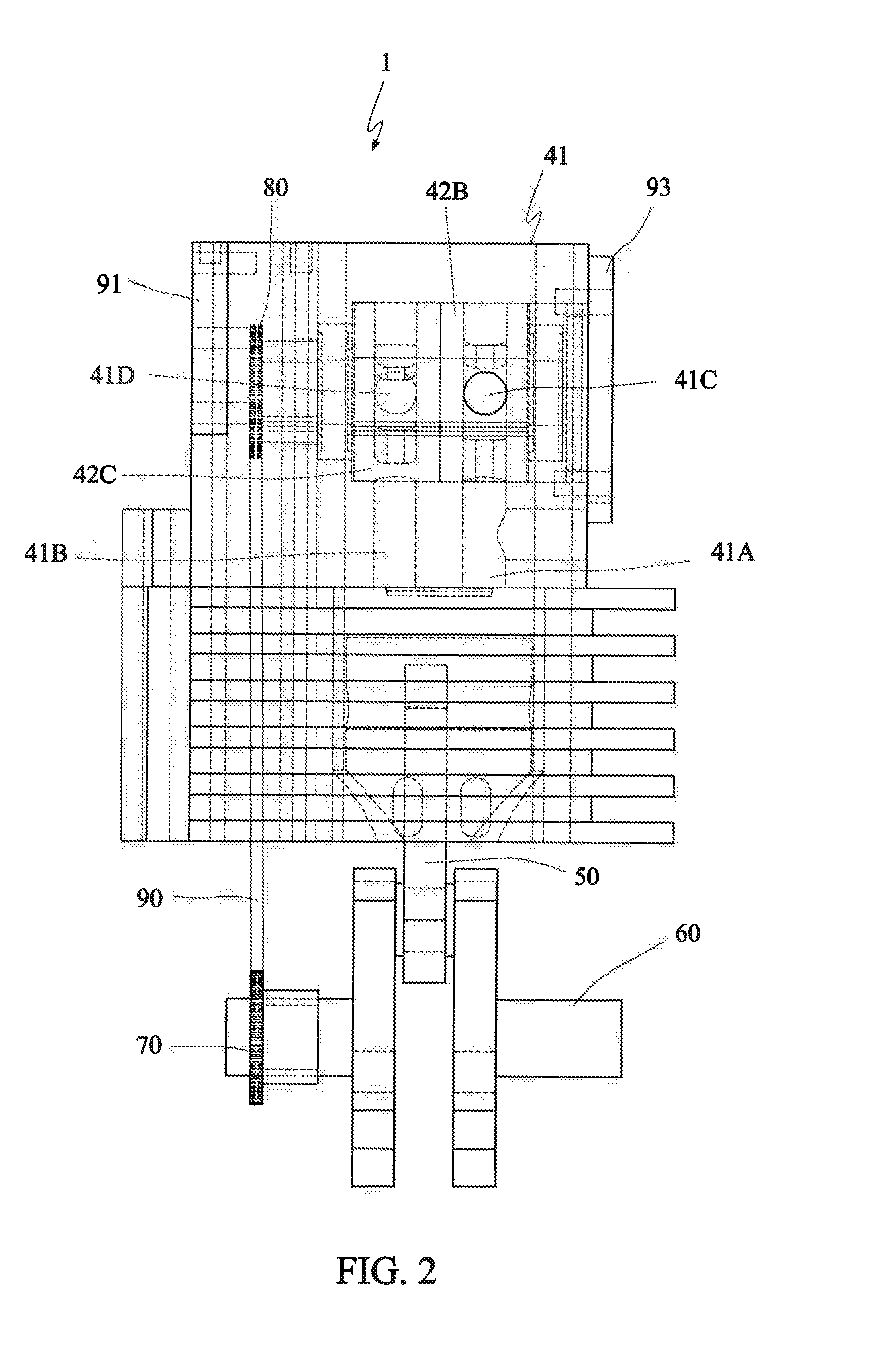
[0039]FIGS. 4C and 4D are schematic illustrations showing an intake state of the air engine at the same time instant according to the invention. In FIGS. 4C and 4D, the intake stroke is depicted, wherein the compressed gas CA enters the intake passage 42B1 of the intake member 42B from the inlet port 41C. At this time, the intake passage 42B1 concurrently communicates with the inlet port 41C and the intake channel 41A, so that the compressed gas CA can enter the cylinder 10 in the path indicated by the arrow, and then push the piston 20 and thus push the crankshaft 60 through the link 50. The crankshaft 60 rotates the crankshaft sprocket 70, and thus rotates the intake-exhaust sprocket 80 through the chain 90. Also, the intake-exhaust sprocket 80 rotates the rotating shaft 42A so that the intake member 42B and the exhaust member 42C are rotated concurrently. In FIG. 4D, the exhaust passage 42C1 contains the exhaust gas EA, generated after the compressed gas CA expands to do the work...

third embodiment

[0046]FIG. 7 is a partial cross-sectional view showing an intake-exhaust assembly according to the invention. As shown in FIG. 7, the rotating shaft 42A may also be coupled to the intake member 42B or the exhaust member 42C using a spline SP. The relative relationship between the intake timing and the exhaust timing is adjusted by adjusting the spline. That is, the rotating shaft 42A may be rotated relatively to the intake member 42B or the exhaust member 42C before the intake member 42B or the exhaust member 42C are mounted on the rotating shaft 42A through the spline SR

[0047]FIGS. 8A to 8C show three examples of intake-exhaust paths according to the invention. In the first embodiment, the included angle A1 between the inlet port 41C and the intake channel 41A is equal to 90 degrees, and the included angle A2 between the outlet port 41D and the exhaust channel 41B is also equal to 90 degrees, as shown in FIG. 8A. In another example, however, the included angles A1 and A2 are equal ...


PUM


Abstract

An air engine includes a cylinder, a piston, a gas supply and an intake-exhaust mechanism. The gas supply supplies a compressed gas to move the piston reciprocating in the cylinder. The intake-exhaust mechanism connected to the cylinder and the gas supply includes a body and an intake-exhaust assembly. The body has a chamber, and an intake channel, an exhaust channel, an inlet port and an outlet port, which communicate with the chamber. The intake-exhaust assembly, rotatable within the chamber, controls the inlet port to be connected to the intake channel, and further controls the outlet port to be connected to the exhaust channel, so that the compressed gas enters the cylinder via the inlet port and the intake channel to drive the piston. After driving the piston, the compressed gas becomes an exhaust gas, which is exhausted from the cylinder via the exhaust channel and the outlet port.

Description

[0001]This application claims priority of No. 102101162 filed in Taiwan R.O.C. on Jan. 11, 2013 under 35 USC 119, the entire content of which is hereby incorporated by reference.BACKGROUND OF THE INVENTION[0002]1. Field of the Invention[0003]The invention relates to an air engine, and more particularly to an air engine with a rotatable intake-exhaust mechanism,[0004]2. Related Art[0005]In a conventional internal combustion engine, rotating cams push an intake valve and an exhaust valve to control intake and exhaust timings, respectively. Because the intake valve and the exhaust valve are trumpet-shaped and the operations are limited by the cam mechanism, the valves need to open and close gradually to complete every cycle. If the internal combustion engine is modified into the air engine, the efficiency of the air engine cannot be effectively enhanced due to the gradually opening and closing operations of the valves.[0006]The air engine (or air motor) converts the pressure energy of ...

Claims


Application Information

Patent Timeline
Patent Type & Authority Applications(United States)
IPC IPC(8): F01B31/00
CPCF01B31/00F01B17/02F01L1/34F01L7/027F01L2250/02F01L2250/06F01L2820/01F01L2303/00
Inventor HUANG, CHIH-YUNGYOU, JHIH-JIESUNG, CHENG-KUOLIN, CHAO-AN
Owner NATIONAL TSING HUA UNIVERSITY
Why Eureka
Try Eureka