Facility for microwave treatment of a load

a load treatment and load technology, applied in microwave heating, electric heating, electric/magnetic/electromagnetic heating, etc., can solve the problems of complicated and restrictive impedance matching, limited impedance matching devices, and high cos

Active Publication Date: 2014-07-17
SAIREM SOC POUR LAPPL IND DE LA RECH & ELECTRONIQUE & MICRO ONDES
View PDF3 Cites 37 Cited by
  • Summary
  • Abstract
  • Description
  • Claims
  • Application Information

AI Technical Summary

Benefits of technology

[0084]The advantage of automated control means is being able to perform an automatic frequency adjustment for each generator, for example until the reflected power PR(i) is minimized on the application devices (i), for impedance matching, monitoring of the transmitted power PT(i) on the application devices (i) and monitoring of the resonance surfaces.
[0085]The embodiment according to the invention is particularly suitable f

Problems solved by technology

These traditional facilities for producing a microwave-excited plasma nevertheless have many drawbacks, which are also encountered in the microwave treatment facilities applied to chemistry in treatment chambers of the reactor type, agri-food in treatment chambers of the heating cavity type, etc.
A first drawback pertains to the limitations inherent to the impedance matching devices 97 to match the independence on each application device, such impedance matching devices furthermore also being used in microwave treatment facilities applied to chemistry, medicine (e.g., treatment of a part of the body, such as a tumor, by microwave radiation), or agri-food (e.g., heating or sterilization of food by microwave radiation.
Thus, the more application devices the installation has, the more complicated and restrictive the impedance matching is, in particular if each application device has its own manual impedance matching device and matching must be done for each application device and optionally for each operating condition.
In this way, the impedance matching will be acceptable for the various operating conditions used during the method, but will not be optimized for each operating condition, unless the user manually redoes the matching each time these operating conditions change.
However, these automatic impedance matching devices are particularly complex and costly due to the electronic control devices, and not very reactive, since they require controlling mechanical elements between several positions.
A second drawback relates to the difficulty of controlling or regulating the power transmitted over each application device, or even distributing the power transmitted between the different application devices equitably; a good distribution for example favoring homogenous heating of an agri-food product or a chemical composition or mixture, in particular to favor volume targeted reactions inside a chemical reactor, or the production of a uniform plasma, in te

Method used


Image

  • Facility for microwave treatment of a load
  • Facility for microwave treatment of a load
  • Facility for microwave treatment of a load

Examples


first embodiment

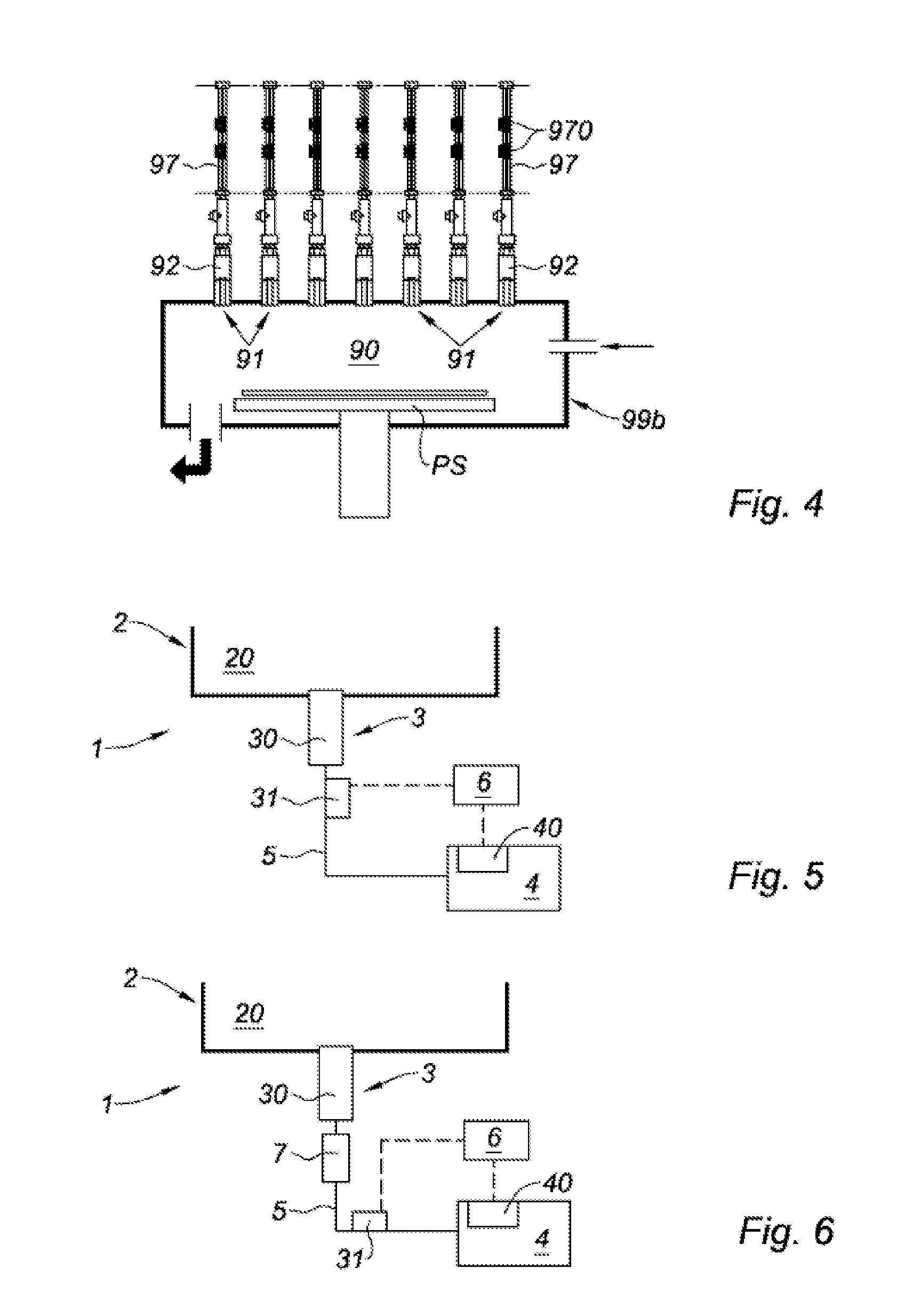
[0158]In the invention illustrated in FIG. 5, the plasma production facility 1 includes:

[0159]a reactor 2 having a treatment chamber 20 in the volume of which the plasma is produced;

[0160]an elementary plasma source 3 comprising an application device 30 applying an electromagnetic wave in the microwave range to the inside of the treatment chamber 20, as well as a measurement system 31 for measuring the power reflected by the application device 30;

[0161]an electromagnetic wave generator 4 in the microwave range, of the solid-state type, connected to the application device 30 by means 5 for guiding the electromagnetic energy, the generator 4 comprising a frequency adjustment system 40 designed to adjust the frequency of the wave between approximately 2400 and 2500 MHz, or even in another predetermined frequency range; and

[0162]a controller 6 connected at the input to the measurement system 31 and at the output to the frequency adjustment system 40.

[0163]For the rest of the description...

third embodiment

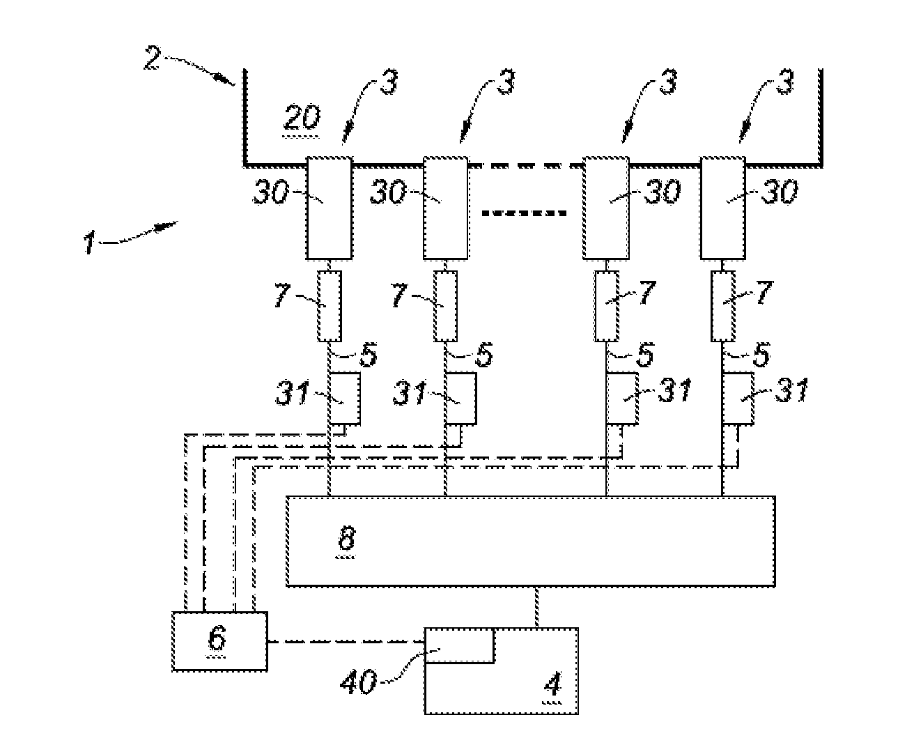
[0202]In the invention illustrated in FIG. 7, the plasma production facility 1 includes:

[0203]a reactor 2 having a treatment chamber 20 in the volume of which the plasma is produced;

[0204]several elementary plasma sources 3 each comprising an applicator 30 inside the treatment chamber 20 applying an electromagnetic wave in the microwave range, as well as a measurement system 31 for measuring the power reflected by the corresponding application device 30;

[0205]an electromagnetic wave generator 4 in the microwave range, of the solid-state type, connected to the applicators 30 by coaxial cables 5, the generator 4 comprising a frequency adjustment system 40 designed to adjust the frequency of the wave between approximately 2400 and 2500 MHz, or even in another predetermined frequency range; and

[0206]a controller 6 connected at the input to the measurement system 31 and at the output to the frequency adjustment system 40; and

[0207]a power divider 8 placed at the output of the generator 4...

sixth embodiment

[0221]In the invention shown in FIG. 10, the plasma production facility 1 includes:

[0222]a reactor 2 having a treatment chamber 20 in the volume of which the plasma is produced;

[0223]several elementary plasma sources 3 each comprising an applicator 30 inside the treatment chamber 20 for applying electromagnetic waves in the microwave range, as well as a measurement system 31 for measuring the power reflected by the corresponding application device 30; and

[0224]several electromagnetic wave generators 4 in the microwave range, of the solid-state type, each connected to an applicator 30 by a coaxial cable 5, with one generator 4 per elementary source 3, each generator 4 comprising a frequency adjustment system 40 designed to adjust the frequency of the wave between approximately 2400 and 2500 MHz, or even in another predetermined frequency range; and

[0225]a controller 6 connected at the input to the measurement systems 31 of the different elementary sources 3 and at the output to the f...


PUM


Abstract

The invention relates to a facility (1) for microwave treatment of a load, including: at least one application device (30); at least one solid-state generator (4) in the field of microwaves, connected to at least one application device by a means for guiding (5) the electromagnetic wave; at least one frequency adjustment system (40) designed for adjusting the frequency of the wave produced by the corresponding generator (4); a measurement system (31) for the or each application device (30), designed for measuring the power reflected P.sub.R(i) by the application device (30); an automated control means (6) connected to each frequency adjustment system (40) and to each measurement system (31) in order to control the adjustment of the frequency f.sub.(i) of the electromagnetic wave according to the reflected power, in order to adjust the reflected power P.sub.R(i) and/or to adjust the transmitted power P.sub.T(i).

Description

TECHNICAL FIELD[0001]The present invention relates to a facility for microwave treatment of a load, and an associated microwave treatment method.[0002]The subject-matter of the invention falls within the field of microwave treatment comprising treating a load absorbing microwaves by applying electromagnetic waves in the microwave range thereon; this load may comprise a liquid, solid or gaseous product having dielectric characteristics allowing it to absorb all or part of the wave, for example such as an aqueous suspension, an agri-food or chemical product, a plasma-forming gas, etc., such a load being able to be contained inside a treatment chamber.[0003]A first application relates to facilities for microwave treatment by producing, in a treatment chamber, a plasma excited by a microwave radiation for various applications, for example and non-limitingly, surface treatment applications, such as etching or material layer deposition, in particular diamond, chemical or thermochemical tr...

Claims


Application Information

Patent Timeline
IPC IPC(8): H01J37/32H05B6/74H05B6/66H05B6/64
CPCH01J37/32266H05B6/664H05B6/74H05B6/6447H01J37/32009H01J37/32192H01J37/32201H01J37/32229H01J37/32302H01J37/32311H01J37/32678
Inventor GRANDEMENGE, ADRIENJACOMINO, JEAN-MARIERADOIU, MARILENALATRASSE, LOUIS
Owner SAIREM SOC POUR LAPPL IND DE LA RECH & ELECTRONIQUE & MICRO ONDES
Why Eureka
Try Eureka