
Monitor system for monitoring the starting of a rotary wing aircraft, an aircraft, and a method using the system

a rotary wing aircraft and monitoring system technology, applied in the direction of aircraft indicators, engine fuctions, analog and hybrid computing, etc., can solve the problems of reducing the work load of the pilot, affecting the flight safety of the aircraft, so as to avoid damage to other mechanical elements, reduce the work load, and avoid the effect of an inciden

Inactive Publication Date: 2014-07-17
EUROCOPTER
View PDF3 Cites 5 Cited by
  • Summary
  • Abstract
  • Description
  • Claims
  • Application Information

AI Technical Summary

Benefits of technology

This patent describes a system that reduces the workload for pilots by eliminating the need to monitor the operation of the rotor. It also prevents damage to other mechanical elements and reduces the risk of incidents in flight by interrupting starting if the freewheel slips. The monitoring system is easy to install and uses a torque-meter shaft and short information transmission channel, resulting in quick and reliable data processing.

Problems solved by technology

Nevertheless, the rollers may become eroded and they might no longer perform their function correctly.
When starting the engine, a worn freewheel can lead to mechanical rupture of the power drive train.
If the driving portion of the freewheel no longer drives the driven portion, then the engine runs the risk of having its free turbine in an overspeed situation.
If mechanical transmission between the driving portion and the driven portion is erratic, then the engine can be subjected to mechanical jolting in the event of the driving and driven portions suddenly re-engaging.
Slip in the freewheel can also lead to abnormal wear of mechanical elements present between the engine and the rotor of the rotary wing, e.g. as a result of repeated jolting.

Method used


Image

  • Monitor system for monitoring the starting of a rotary wing aircraft, an aircraft, and a method using the system
  • Monitor system for monitoring the starting of a rotary wing aircraft, an aircraft, and a method using the system

Examples


Embodiment Construction

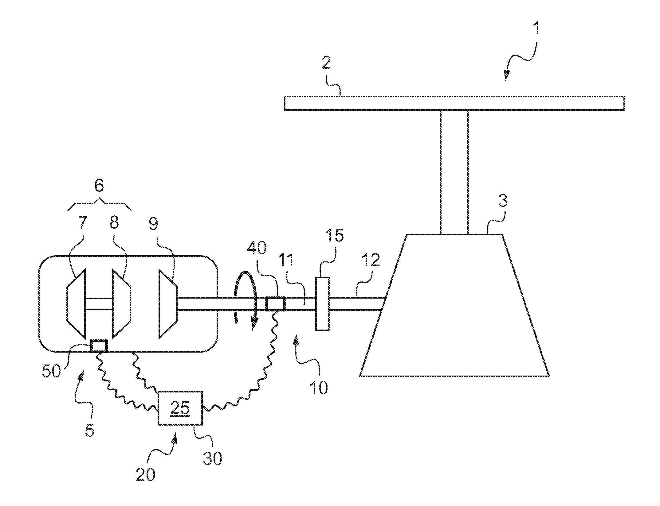
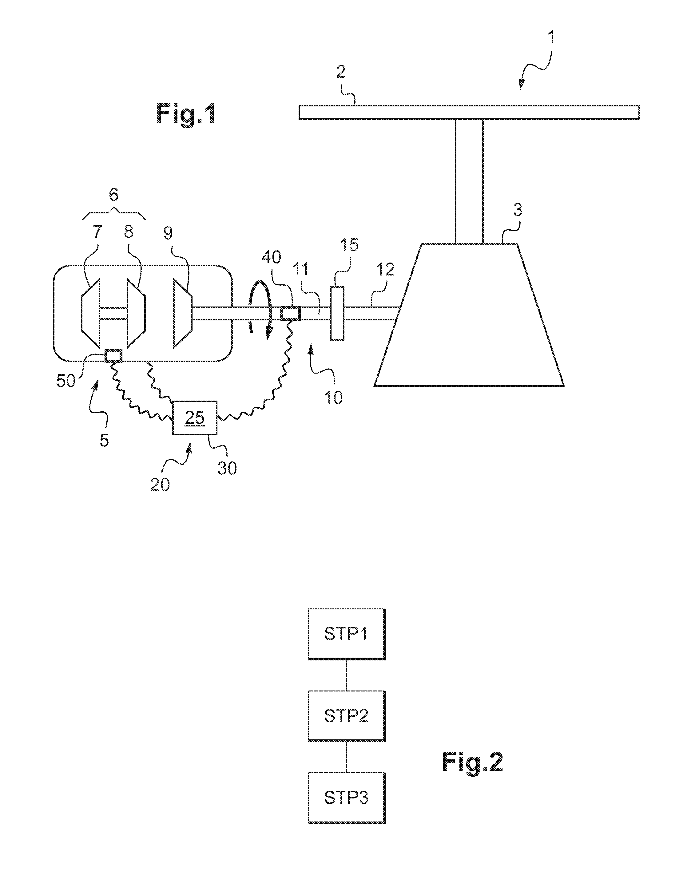
[0045]FIG. 1 shows an aircraft 1 of the invention.

[0046]The aircraft 1 includes a rotary wing having at least one rotor 2.

[0047]In order to set the rotary wing into rotation, the aircraft 1 has at least one turboshaft engine 5 and a main gearbox 3. The engine 5 then drives the main gearbox 3 via a drive train 10 for transmitting power, the main gearbox 3 than setting the rotor 2 in rotation.

[0048]The engine 5 has a gas generator 6. The gas generator is conventionally provided with a compressor 7 associated with a high pressure turbine 8.

[0049]The engine also has a free turbine 9. The gas coming from the gas generator 6 serves to set the free turbine 9 into rotation.

[0050]Consequently, the drive train 10 for transmitting power includes at least one shaft connecting the free turbine to the main gearbox 3. This drive train 10 for transmitting power also possesses a freewheel 15.

[0051]Thus, the drive train 10 has an upstream portion 11 connecting the free turbine 9 to a driving portion ...


PUM


Abstract

A method of starting a turboshaft engine (5) of an aircraft (1), said aircraft (1) being provided with a rotary wing, said aircraft (1) having a freewheel (15) interposed in a drive train (10) between said engine (5) and a rotor (2) of said rotary wing (1), said engine (5) comprising a gas generator (6) and a free turbine (9), the drive train (10) including an upstream portion (11) connecting said free turbine (9) to said freewheel (15), the method comprising the following steps: measuring the torque (Tq) exerted on said upstream portion (11), and measuring a speed of rotation (Ng) of said gas generator (6); comparing said torque (Tq) with a torque threshold (Stq) and comparing said speed of rotation (Ng) with a speed threshold (Sng); and stopping said engine (5) when said torque (Tq) is less than the torque threshold (Stq) and when said speed of rotation (Ng) is greater than the speed threshold (Sng).

Description

CROSS REFERENCE TO RELATED APPLICATION[0001]This application claims priority to French patent application No. FR 13 00081 filed on Jan. 16, 2013, the disclosure of which is incorporated in its entirety by reference herein.BACKGROUND OF THE INVENTION[0002](1) Field of the Invention[0003]The present invention relates to a monitor system for monitoring the starting of a rotary wing aircraft. The invention also relates to a rotary wing aircraft fitted with such a system and to a method of starting a turboshaft engine that make use of the monitor system.[0004]The invention thus lies in the field of devices for monitoring the power plant of rotary wing aircraft.[0005](2) Description of Related Art[0006]Conventionally, a rotary wing aircraft has a power plant provided with a rotor that provides at least some of the lift of the aircraft. The rotor may also contribute to providing at least some of the propulsion of the aircraft. Thus, a helicopter has a main rotor that provides it both with ...

Claims


Application Information

Patent Timeline
IPC IPC(8): B64D45/00
CPCB64D45/00F02C6/206F02C7/26F02C9/00F05D2260/80F05D2260/85F05D2220/329
Inventor MASSOT, LUCIE
Owner EUROCOPTER
Learn More