Vehicle control apparatus

a technology for controlling apparatus and vehicles, applied in the direction of instruments, analogue processes, and specific applications using reradiation, can solve the problems of putting unneeded stress on the driver, and achieve the effect of reducing the stress on the driver

Active Publication Date: 2014-07-17
NISSAN MOTOR CO LTD
View PDF31 Cites 14 Cited by
  • Summary
  • Abstract
  • Description
  • Claims
  • Application Information

AI Technical Summary

Benefits of technology

[0009]According to the present invention, adjusting at least one of the first risk and the second risk, and preferentially executing a warning or vehicle control regarding

Problems solved by technology

However, since an alarm buzzer will certainly sound when each of the sensors detect an obstacle, the above mentioned on-board obstacle sensing system may

Method used


Image

  • Vehicle control apparatus
  • Vehicle control apparatus
  • Vehicle control apparatus

Examples


first embodiment

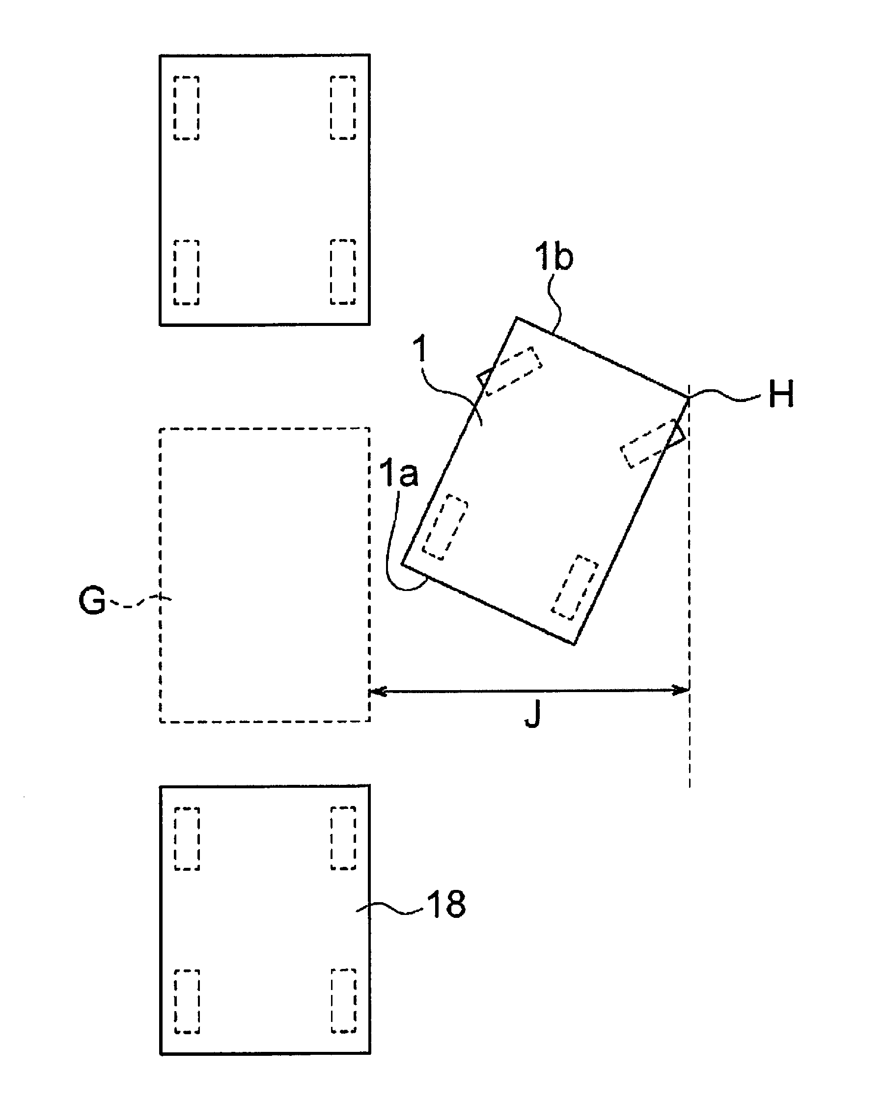
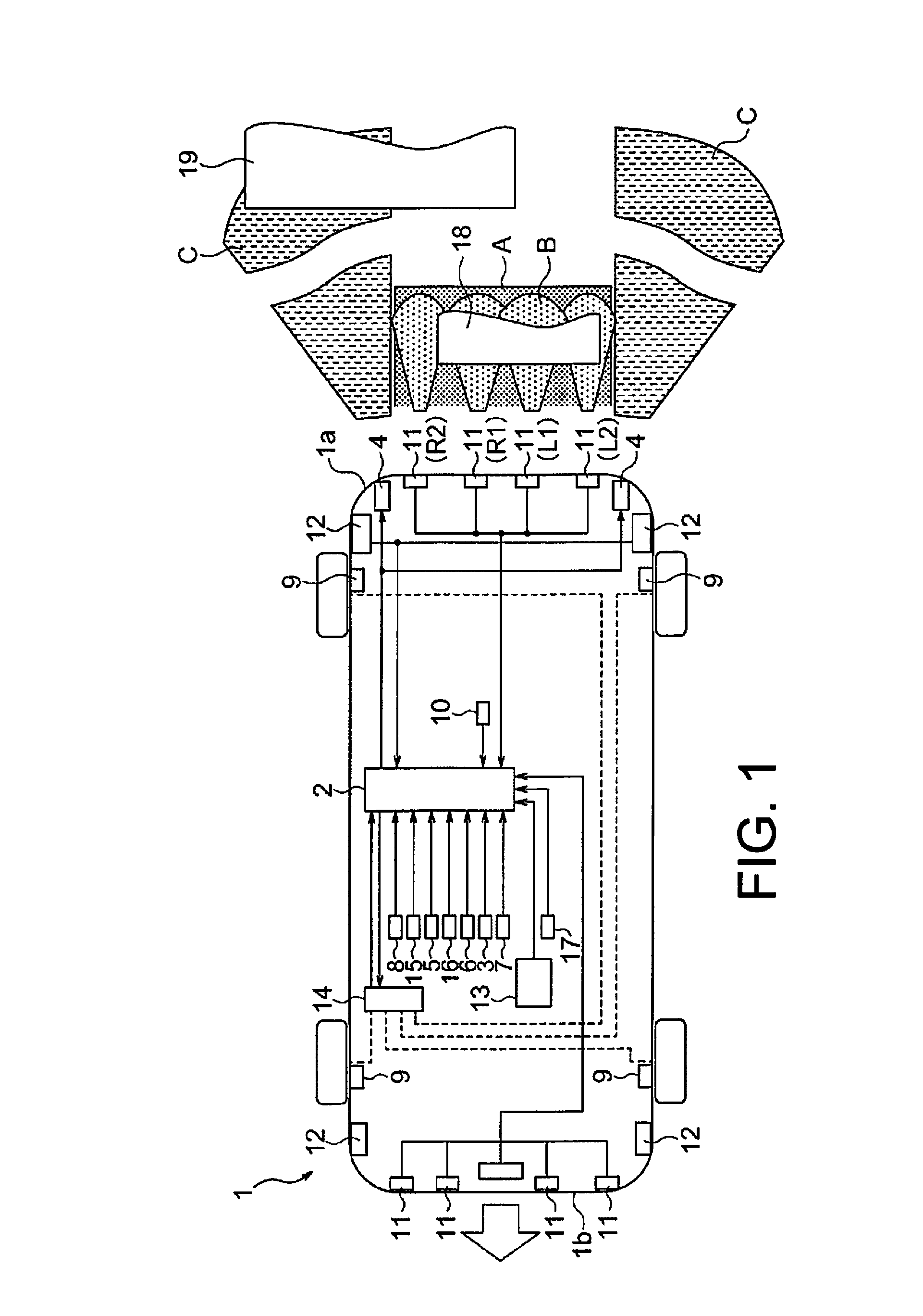
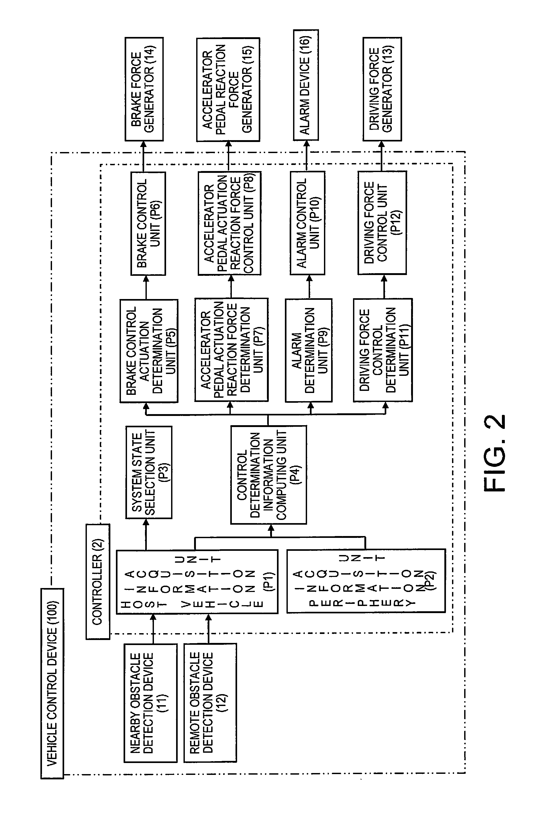
[0040]FIG. 1 is a schematic view of a vehicle in the present embodiment; FIG. 2 is a block diagram of a vehicle control device in the present embodiment; FIG. 3 is a block diagram of the host vehicle information acquisition unit of FIG. 2; and FIG. 4 to FIG. 8 are diagrams for explaining the parking state determination made by the parking state evaluation unit in the present embodiment.

[0041]As illustrated in FIG. 1, the vehicle 1 in the present embodiment is provided with a controller 2, a switch sensor 3, a brake lamp 4, an accelerator position sensor 5, a brake pedal position sensor 6, a shift position sensor 7, a steering sensor 8, a wheel speed sensor 9, an acceleration and deceleration sensor 10, a nearby obstacle detection device 11, a remote obstacle detection device 12, a driving force generator 13, a brake force generator 14, an accelerator pedal reaction force generator 15, an alarm device 16, and an ignition switch 17. The respective sensors, devices, and so forth will b...

second embodiment

[0177]FIG. 19 is a block diagram of the host vehicle information acquisition unit in the present embodiment; FIG. 20 and FIG. 21 are diagrams for explaining the operation of the position and attitude detection unit in the present embodiment; FIG. 22 is a block diagram of the control determination information computing unit in the present embodiment; FIG. 23 is a graph for explaining the third risk gain in the present embodiment; and FIG. 24 is a graph for explaining a fourth risk gain in the present embodiment.

[0178]In the present embodiment, although the configuration of the host vehicle information acquisition unit P1 and the control determination information computing unit P4 in the controller 2 differs from the first embodiment, all other aspects are the same as the first embodiment. Only those portions that differ from the first embodiment will be described below, while portions that are the same as the first embodiment will be given the same reference numerals with the explana...

third embodiment

[0202]FIG. 25 is a graph for explaining the fixed of fifth risk gain in the present embodiment; and FIG. 26 is a graph for explaining a sixth risk gain in the present embodiment.

[0203]Although in the present embodiment the configuration of the position and attitude detection unit P110 and the second risk adjustment unit P405 differ from the second embodiment, all other aspects are the same as the second embodiment. That is, the present embodiment is the same as the first embodiment except for the controller 2 having the position and attitude detection unit P110 and the second risk adjustment unit P405. Only the portions that differ from the first and the second embodiments will be described below; the portions that are the same as the first and the second embodiments will be given the same reference numerals, and explanations therefor will be omitted. Additionally, the display of reference numerals regarding the first and second risks will be omitted as with the second embodiment.

[0...


PUM


Abstract

A vehicle control device basically includes a first risk computation unit, a second risk computing unit and a first risk adjustment unit. The first risk computation unit calculates a first risk with respect to a nearby obstacle located in a nearby detection region near a host vehicle. The second risk computing unit calculates a second risk with respect to a remote obstacle located further from the nearby detection region. The first risk adjustment unit adjusts at least one of the first and the second risks to preferentially execute a warning or vehicle control based on one of the first risk or the second risk versus a warning or vehicle control based on the other of the first risk or the second risk based on an entry state of the host vehicle of entering a planned parking place, or an exit state of the host vehicle of exiting from a parking place.

Description

CROSS-REFERENCE TO RELATED APPLICATIONS[0001]This application is a U.S. National stage application of International Application No. PCT / JP2012 / 073922, filed Sep. 19, 2012, which claims priority under to Japanese Patent Application No. 2011-206845 filed in Japan on Sep. 22, 2011.BACKGROUND[0002]1. Field of the Invention[0003]The present invention relates to a vehicle control device that produces a warning or carries out vehicle control regarding an obstacle.[0004]2. Background Information Background Art[0005]There is known an on-board obstacle sensing system that detects obstacles using an electromagnetic wave sensor and an ultrasonic sensor (refer to, for example, Japanese Unexamined Patent Publication No. H11-301383).SUMMARY[0006]However, since an alarm buzzer will certainly sound when each of the sensors detect an obstacle, the above mentioned on-board obstacle sensing system may execute a warning for obstacles that have little possibility of contacting a vehicle, and has the disa...

Claims


Application Information

Patent Timeline
IPC IPC(8): G08G1/16G01S15/931
CPCG08G1/168B62D15/027G08G1/166B60Q9/006G01S2015/938G01S15/931G01S2015/932G01S2013/9319G01S2013/93185G01S2013/932B60W30/08B60W30/0956B60W30/18009B60W30/18027
Inventor SUGANO, TAKESHIKOBAYASHI, MASAHIROGOKAN, TOSHIMICHI
Owner NISSAN MOTOR CO LTD
Why Eureka
Try Eureka