Engine cover plate

a technology for engine covers and covers, applied in engine cooling devices, valve arrangements, machines/engines, etc., can solve problems such as loss of fluid flow control, and achieve the effect of reducing overheating

Active Publication Date: 2014-07-24
FORD GLOBAL TECH LLC
View PDF11 Cites 9 Cited by
  • Summary
  • Abstract
  • Description
  • Claims
  • Application Information

AI Technical Summary

Benefits of technology

[0001]Internal combustion engines, such as those found in vehicles, may utilize a cooling circuit to reduce over-heating. This may be achieved by a combination of engine oil cooling and liquid coolant cooling.
[0003]Conventionally, coolant fluid pumps are mounted onto the engine block surface and coupled to the engine water jacket. The high-pressure die casting manufacturing method used for engine production relies on the coolant passageways being linear. One way in which coolant exiting the coolant pump may be coupled to the water jacket using linear paths is by the creation of a cavity on the outside of the engine block sealed by a cover plate. In this way the coolant path can change direction without leaving the engine block. Conventional coolant cavities have a water pump outlet that opens into one side of the coolant cavity, and another side that is open to the water jacket. However, the inventors recognized that this abrupt change in coolant flow direction creates losses in fluid flow control.
[0004]This issue may be addressed by creating a coolant cavity configuration and cover plate to direct the flow of coolant from the water pump outlet port to the water jacket inlet port down a slope, thus decreasing flow control losses. In one example, a system for engine cooling comprises: a cover plate for a coolant passage, the plate including a coolant outlet port displaced away from a coolant inlet port, and a plurality of oil ports; and a coolant cavity, covered by the cover plate, within the coolant passage and coupled to a fluid pump and a water jacket.
[0005]Various additional advantages may be achieved in some embodiments. For example, the cover plate may enable reduction of the number of engine block components while meeting the increased demand on the cooling system by integrating a port for engine oil to enter the engine block via an attached valve. In doing so, the proximity of the engine oil and coolant is reduced and undesired heat absorption into the cooling system reduced to provide more effective cooling. The system may also reduce the need for an additional port and valve arrangement to pass oil into the engine block. Further, by actuating the oil valve in response to temperature sensors within the oil circuit, engine heating to a desired operating threshold can be expedited. Additional ports optionally incorporated into this cover plate also provide a solution to the distribution of oil and coolant to turbochargers, EGR, and other systems.

Problems solved by technology

However, the inventors recognized that this abrupt change in coolant flow direction creates losses in fluid flow control.

Method used


Image

  • Engine cover plate
  • Engine cover plate
  • Engine cover plate

Examples


Embodiment Construction

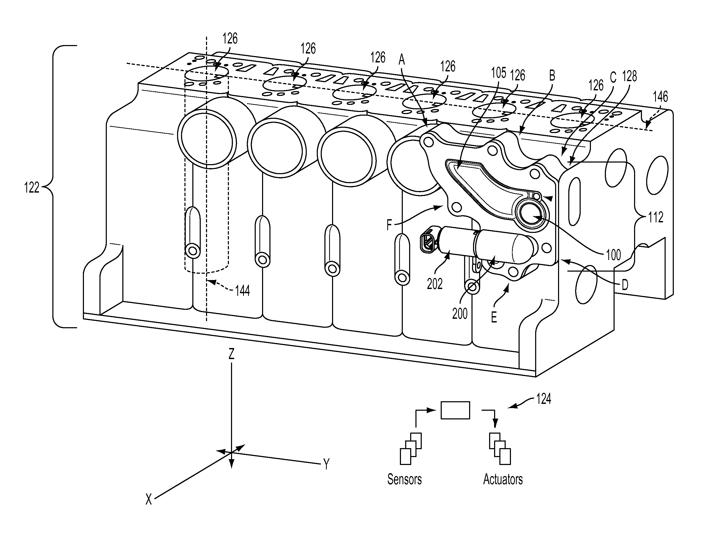
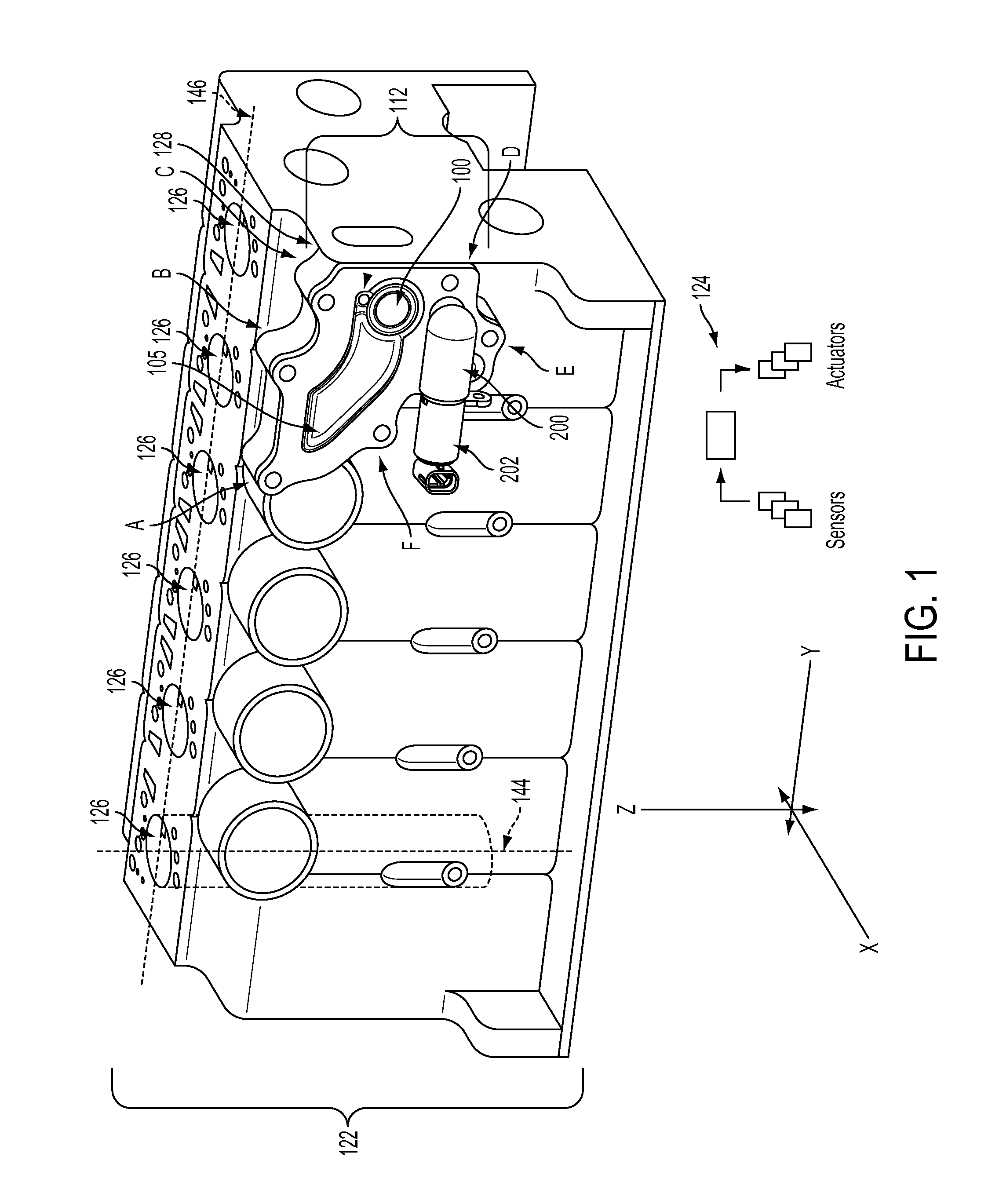
[0023]The subject matter of the present disclosure is now described by way of example and with reference to certain illustrated embodiments. It will be noted that figures included in this disclosure are schematic, and are identified as such. In the schematic figures, views of the illustrated embodiments are all not drawn to scale; aspect ratios, feature size, and numbers of features may be purposely distorted to make selected features or relationships easier to see.

[0024]Methods and systems are provided for an engine block configuration and coolant cavity cover plate with integrated engine oil and coolant fluid coupling. FIG. 1 shows an example engine block 122 configuration compatible with the cover plate and an example cover plate 112. Coolant exiting a fluid pump is contained within the engine block by a cover plate bolted to a coolant cavity on the outer face of engine block. The cover plate also acts to fluidically couple the fluid pump to an engine water jacket opening. The in...


PUM


Abstract

A engine block cover plate is described having a depression shaped to guide coolant flow around a bend in a coolant circuit, the plate further including a plurality of oil ports. One example method of operation may include guiding a coolant flow around a bend in a cooling circuit within an engine block via the cover plate, the cover plate having coolant and oil ports positioned therein, and adjusting a valve positioned on the cover plate to control a flow of oil through the oil port in response to an engine component temperature. In this way, flow losses may be decreased while enabling improved oil flow control with reduced system complexity.

Description

BACKGROUND AND SUMMARY[0001]Internal combustion engines, such as those found in vehicles, may utilize a cooling circuit to reduce over-heating. This may be achieved by a combination of engine oil cooling and liquid coolant cooling.[0002]Liquid coolant absorbs excess heat from combustion and transfers the heat into the air or cabin of the vehicle via respective heat exchangers, such as a radiator and heater core. However, liquid coolant is isolated from the combustion chambers in order for ignition to occur; heat is therefore exchanged via conductive metal passageways surrounding the combustion chambers. These isolating passageways may be referred to as the water jacket. Coolant is accelerated through the engine by way of a fluid pump before entering the water jacket; this closed coolant circulation pathway referred to as the coolant circuit. Engine oil may undergo a similar heat exchange process within a separate circuit wherein oil is accelerated by an oil pump coupled to an oil in...

Claims


Application Information

Patent Timeline
Patent Type & Authority Applications(United States)
IPC IPC(8): F01P11/08
CPCF01P11/08F01P2060/16
Inventor MAKI, CLIFFPOLLEY, THOMASMULLINS, JEFFREY ALLENSTANLEY, SONNY E.
Owner FORD GLOBAL TECH LLC
Why Eureka
Try Eureka