Light control panel

a technology of light control panel and control panel, which is applied in the direction of door/window protective device, curtain suspension device, instrument, etc., can solve the problems of low transparency of suspended particle device, low transparency of open suspended particle device,

Inactive Publication Date: 2014-07-24
KONINKLIJKE PHILIPS ELECTRONICS NV
View PDF0 Cites 127 Cited by
  • Summary
  • Abstract
  • Description
  • Claims
  • Application Information

AI Technical Summary

Benefits of technology

[0006]It is an object of the present invention to overcome this problem, and to provide energy-efficient light control devices and methods which avoid at least some of the drawbacks of the prior art.

Problems solved by technology

However, smart windows using electrochromic layers have a colored appearance, which may be undesirable for many applications.
Furthermore, suspended particle devices suffer from low transparency in the “open” state, due to light absorption by the particles also in the aligned state.
Although claimed to be invisible, the microblinds described in U.S. Pat. No. 7,684,105 result in unacceptably low transparency in the curled configuration, and they may not be suitable for large-scale production.

Method used


Image

  • Light control panel
  • Light control panel
  • Light control panel

Examples


Embodiment Construction

[0042]The present inventors have found that light control panel as described below can advantageously be used in windows etc. for combined light transmission control and energy saving.

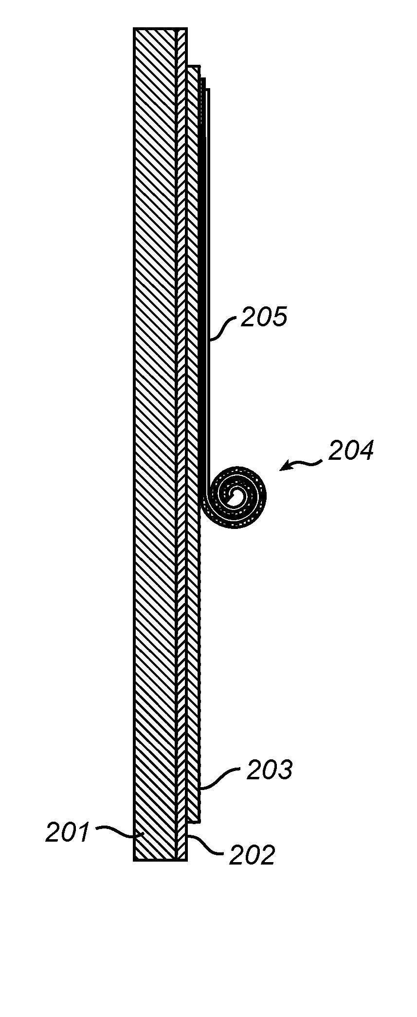
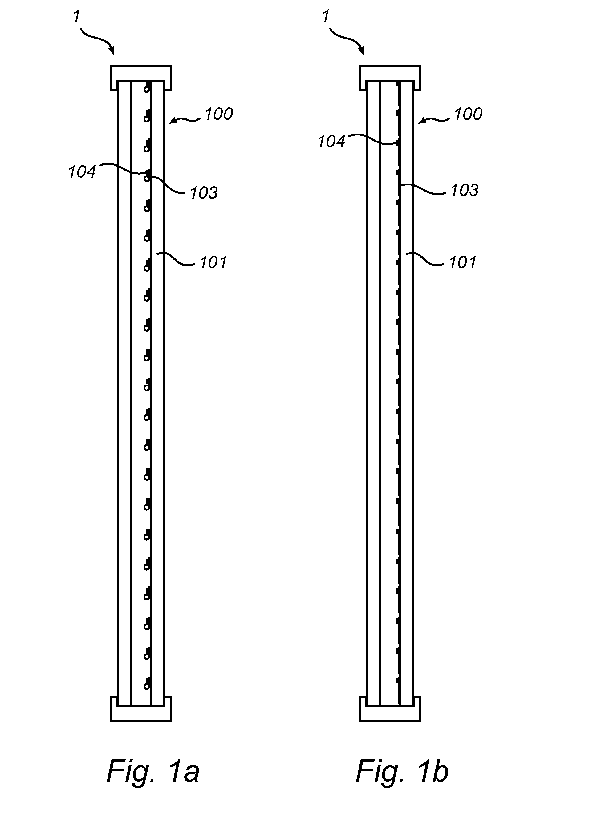
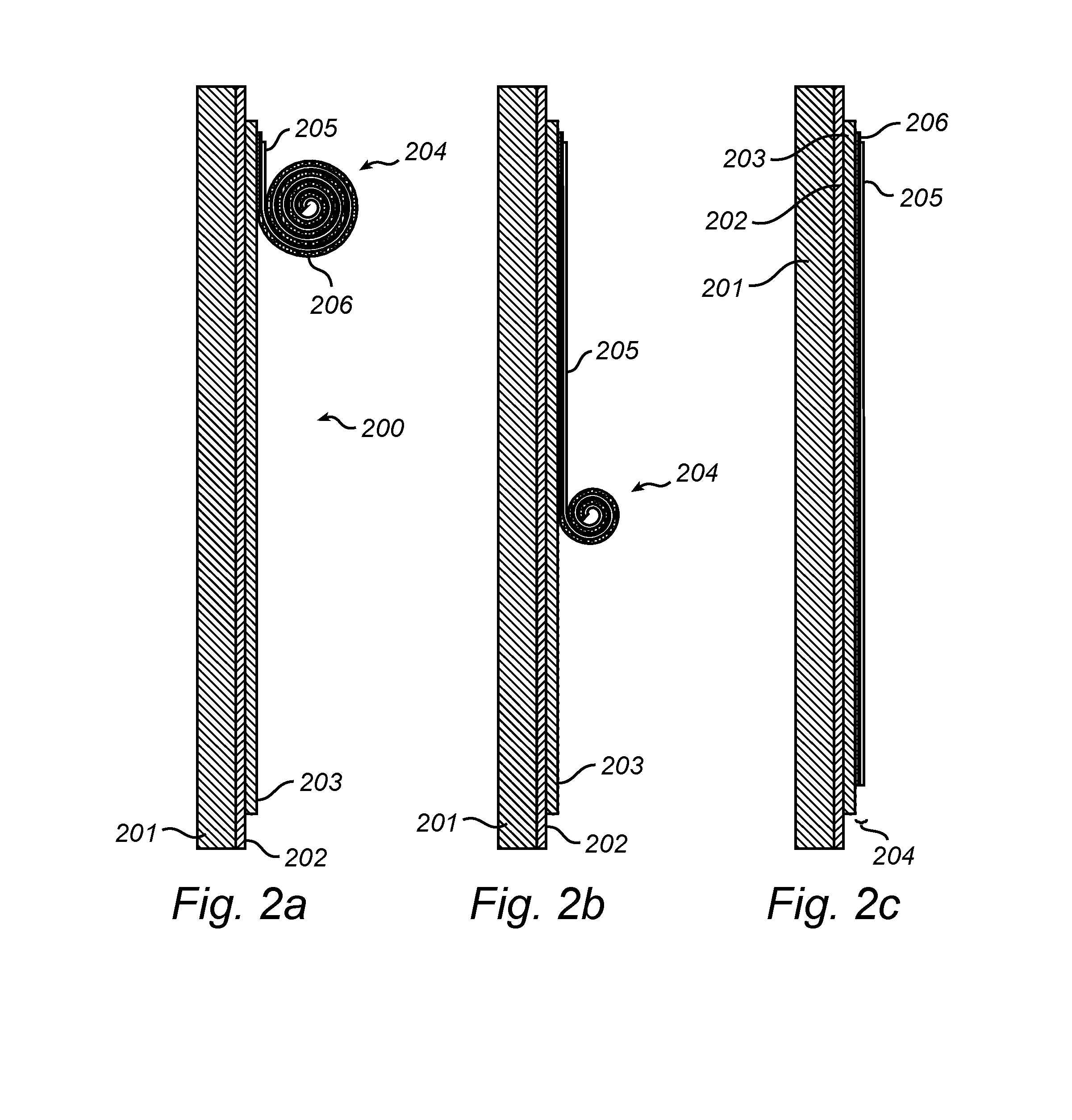
[0043]FIGS. 1a-b illustrate a light control panel comprising an array of electrically controllable thin film roll-up blinds. The light control panel 100 of this embodiment forms part of a double glaze glass window 1. The panel 100 comprises a transmissive substrate 101, typically a glass plate, on which is arranged a plurality of thin film roll-up blinds 103. Each roll-up blind 103 has a naturally rolled-up configuration and may be reversibly unrolled (FIG. 1b) in response to the application of an electric potential. In the unrolled, planar configuration (FIG. 1b) the roll-up blind 103 covers a larger part of the substrate 101 compared to its rolled-up configuration and the roll-up blind 103 itself is maximally exposed e.g. in order to receive incident radiation. When the electric potential is removed,...


PUM

PropertyMeasurementUnit
wavelength rangeaaaaaaaaaa
wavelengthsaaaaaaaaaa

Abstract

Alight control panel is provided, comprising: a transmissive substrate; a transmissive electrically conductive layer arranged on a surface of said substrate; a transmissive dielectric layer arranged on said electrically conductive layer; a flexible roll-up blind attached to said dielectric layer, said flexible roll-up blind layer comprising a flexible electrically conductive layer and a flexible optically functional layer, said flexible layer having naturally a rolled configuration and being capable of unrolling in response to electrostatic force; and an optoelectronic device. The panel may be useful in various energy saving applications including smart windows for buildings or vehicles, e.g. providing an energy efficient light source or utilizing solar radiation for energy conversion.

Description

FIELD OF THE INVENTION[0001]The present invention relates to the field of light control using electrically controlled thin film roll-up blinds.BACKGROUND OF THE INVENTION[0002]Daylight entering a house or building is traditionally controlled using window roll-up blinds or shutters that are operated manually or by motors. Where windows must keep a certain degree of transparency, for example in vehicles, permanently shaded (tinted) windowpanes are often used to reduce light and heat transmission. Energy saving aspects of daylight control for buildings and vehicles is today also becoming increasingly important. For example, in order to reduce the energy spent on climate control, it is desirable to allow control of the amount of sunlight and heat entering a building though the windows. It is also desirable to be able to control the amount of light and / or heat exiting a building.[0003]In recent years, so-called smart windows have been developed, which allow light transmission control usi...

Claims


Application Information

Patent Timeline
Patent Type & Authority Applications(United States)
IPC IPC(8): E06B9/40B32B38/00G02B26/02
CPCE06B9/40B32B38/0004G02B26/02E06B9/68E04F10/02E06B2009/2405E06B2009/2417E06B2009/247E06B2009/2476E06B2009/6818E06B2009/6827B60J1/2019E06B2009/2643Y10T156/1052
Inventor HIKMET, RIFAT ATA MUSTAFAVAN BOMMEL, TIESANSEMS, WILHELMUS JOHANNES HENDRICUSTIMMERING, CORNELIS EUSTATIUSVAN GLABBEEK, JACOBUS JOHANNES
Owner KONINKLIJKE PHILIPS ELECTRONICS NV
Why Eureka
Try Eureka