
Collector device of electric train and collector method thereof

a technology of electric trains and collectors, applied in electric vehicles, vehicle components, electric vehicles, etc., can solve problems such as uneven contact surfaces, electric arc phenomena, and prone to occuring electric arc phenomena, and achieve the effect of enhancing the power transmission quality of electric trains

Active Publication Date: 2014-07-24
NAT TAIWAN UNIV OF SCI & TECH
View PDF4 Cites 16 Cited by
  • Summary
  • Abstract
  • Description
  • Claims
  • Application Information

AI Technical Summary

Benefits of technology

The invention provides a collector device for an electric train that includes a collector unit and a magnetic unit. The collector unit has a graphite skateboard that comes into contact with a power source to draw an operation voltage. The magnetic unit is positioned on the second side of the collector unit to create an attractive force between these two components to reduce contact loss and improve power transmission. This solution helps to prevent electric arc formation, reduce depletions of the collector unit and power source, and enhance power transmission quality.

Problems solved by technology

However, under influences of shaking during high-speed driving, irregularity of the trolley wire, vibrations of the trolley wire and a graphite skateboard, or unevenness of rails, a contact loss situation among the pantograph and the trolley wire is prone to occur, and thereby resulting in an electric arc phenomenon.
Generally, the higher the speed of the electric train, the greater the possible for the pantograph and the trolley wire to be separated, and the electric arc phenomenon is prone to occur.
The electric arc phenomenon may result in unevenness for a contact surface of the graphite skateboard and influence a power supply quality.
Moreover, the electric arc also influences the service life of the graphite skateboard and increases a replacement number thereof, and when it is severe, the trolley wire may be damaged and thereby affect train safety.

Method used


Image

  • Collector device of electric train and collector method thereof
  • Collector device of electric train and collector method thereof
  • Collector device of electric train and collector method thereof

Examples


Embodiment Construction

[0025]Reference will now be made in detail to the exemplary embodiments of the invention, examples of which are illustrated in the accompanying drawings. Moreover, elements / components with the same or similar reference numerals represent the same or similar parts in the drawings and embodiments.

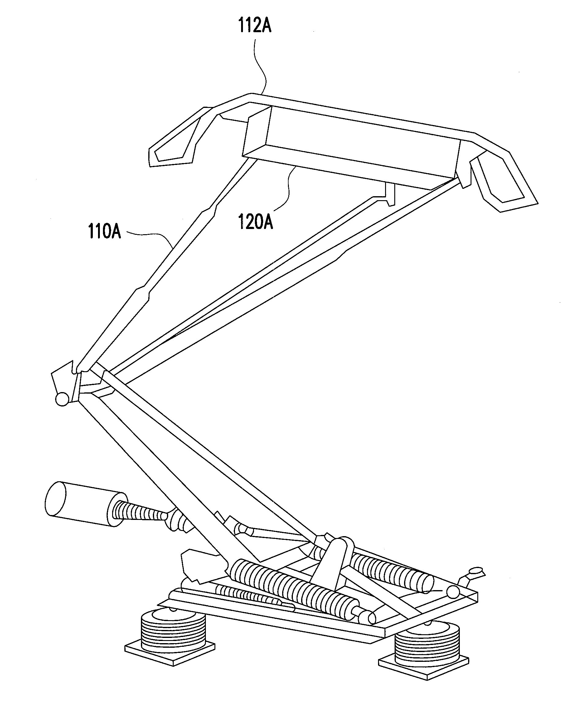
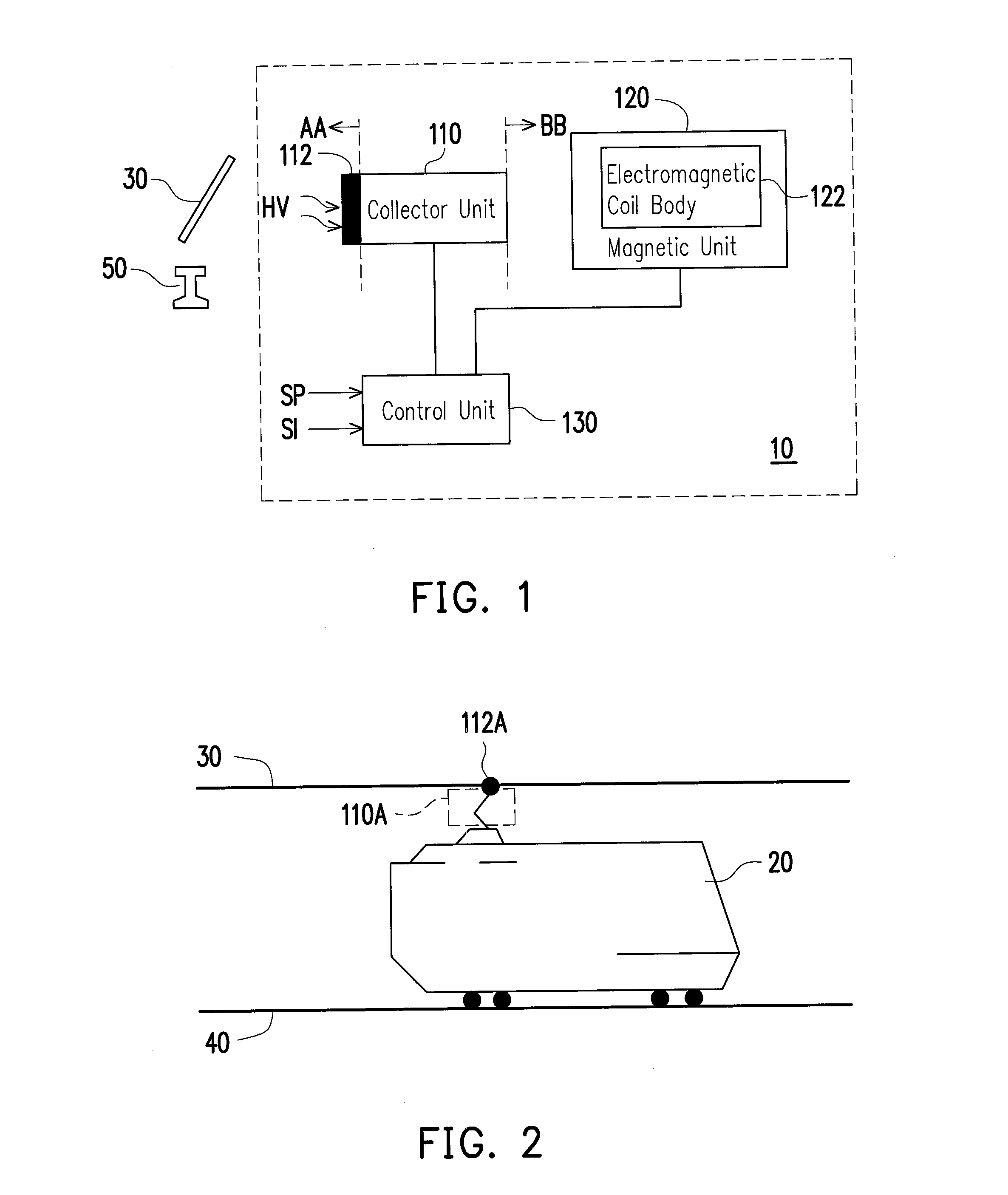
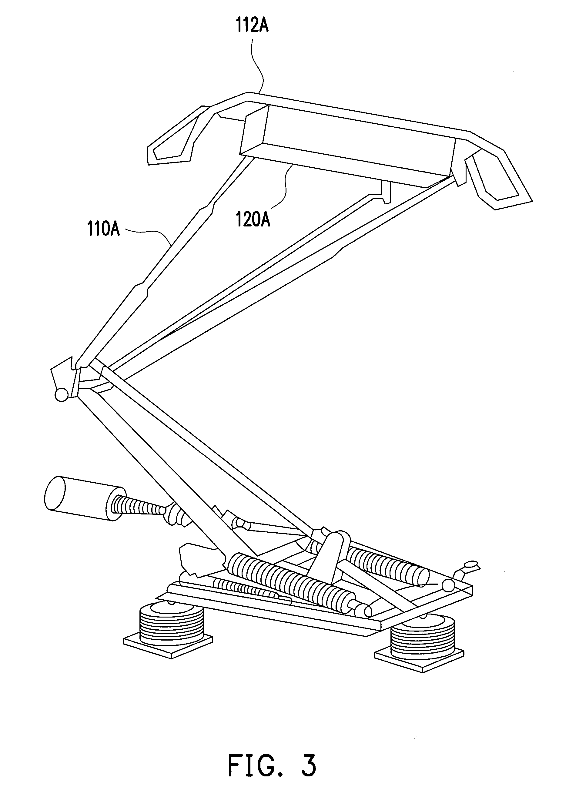
[0026]FIG. 1 is a schematic view illustrating a collector device of an electric train according to an embodiment of the invention. FIG. 2 is a schematic view illustrating a trolley wire of the electric train according to the embodiment of the invention. Referring FIG. 1 and FIG. 2 in combination, a collector device 10 of an electric train 20 includes a collector unit 110 and a magnetic unit 120. The collector unit 110 has a first side AA, a second side BB and a graphite skateboard 112, wherein the first side AA and the second side BB are the two opposite sides of the collector unit 110, and the graphite skateboard 112 is preferably disposed on the first side AA. When the first side AA of the ...


PUM


Abstract

A collector device of an electric train and a collector method thereof are provided. The collector device includes a collector unit and a magnetic unit. The collector unit has a first side, a second side and a graphite skateboard. The first side and the second side are the two opposite sides of the collector unit, and the graphite skateboard is disposed on the first side, wherein the first side of the collector unit is in contact with a power source having a magnetically permeable capacity via the graphite skateboard, so as to draw an operation voltage. The magnetic unit has an electromagnetic coil body. The magnetic unit is configured on the second side of the collector unit, for providing an attractive force between the collector unit with the power source, so as to reduce a contact loss rate.

Description

CROSS-REFERENCE TO RELATED APPLICATION[0001]This application claims the priority benefit of Taiwan application serial no. 102102068, filed on Jan. 18, 2013. The entirety of the above-mentioned patent application is hereby incorporated by reference herein and made a part of this specification.BACKGROUND[0002]1. Field of the Application[0003]The invention relates to a power transmission technology of an electric train, and more particularly, to a collector device of an electric train and a collector method thereof.[0004]2. Description of Related Art[0005]In an electrified railway power supply system, an electric train uses a pantograph to be in contact with a trolley wire, so as to introduce power into a main transformer of the electric as a power source of the electric train. However, under influences of shaking during high-speed driving, irregularity of the trolley wire, vibrations of the trolley wire and a graphite skateboard, or unevenness of rails, a contact loss situation among ...

Claims


Application Information

Patent Timeline
IPC IPC(8): B60L5/24
CPCB60L5/20B60L5/38B60L2200/26
Inventor KUO, MING-TSELO, WEN-YIWANG, YAO-YI
Owner NAT TAIWAN UNIV OF SCI & TECH
Learn More