Positioning control system for actuator provided with wave gear device

a technology of wave gear and positioning control system, which is applied in the direction of gearing, program control, instruments, etc., can solve the problems of steady state deviation or vibration, and achieve the effect of shortening the positioning time, suppressing the angular transmission error, and improving the positioning performance of the positioning mechanism

Active Publication Date: 2014-07-24
HARMONIC DRIVE SYST IND CO LTD +1
View PDF5 Cites 13 Cited by
  • Summary
  • Abstract
  • Description
  • Claims
  • Application Information

AI Technical Summary

Benefits of technology

[0017]The present invention proposes a model base control system for nonlinear spring characteristics, a relative rotation-synchronous component, and nonlinear friction, which are nonlinear characteristics of a wave gear device, for the purpose of improving positioning performance of a positioning mechanism that includes the wave gear device. Modeling is performed as a differentiable function on these nonlinear characteristics, and a positioning control system is designed which uses feedforward compensation based on exact linearization. According to the system of the present invention, overshooting caused by nonlinear springs and nonlinear friction can be inhibited to shorten positioning time in the operation of positioning an actuator provided with a wave gear device, and response contained vibration and load positioning variation during stabilizing due to angular transmission error can be suppressed,

Problems solved by technology

The vibration or angular transmission error (relative rotation-synchronous component) that occurs synchronously with rotation due to gear machining errors or assembly errors causes steady state deviation or vibration, particularly in the load position of the semi-closed loop control system.

Method used


Image

  • Positioning control system for actuator provided with wave gear device
  • Positioning control system for actuator provided with wave gear device
  • Positioning control system for actuator provided with wave gear device

Examples


experiment verification

[Experiment Verification of Nonlinear Compensation]

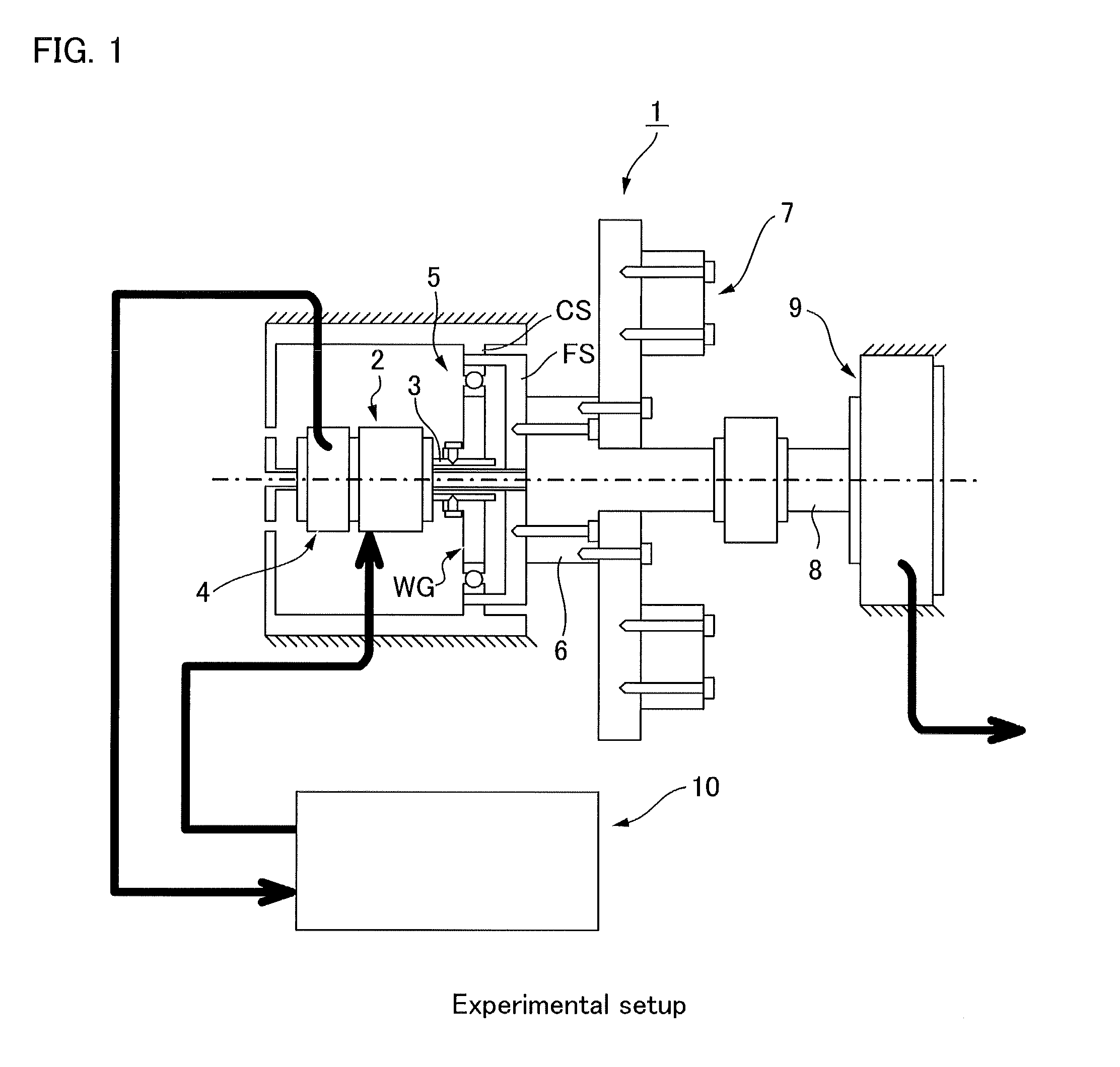
[0077]A positioning control system constructed as described above for performing nonlinear compensation based on an exact linearization method was implemented in an experiment positioning control system, and the compensation effects thereof were verified through testing.

(Positioning Test Conditions)

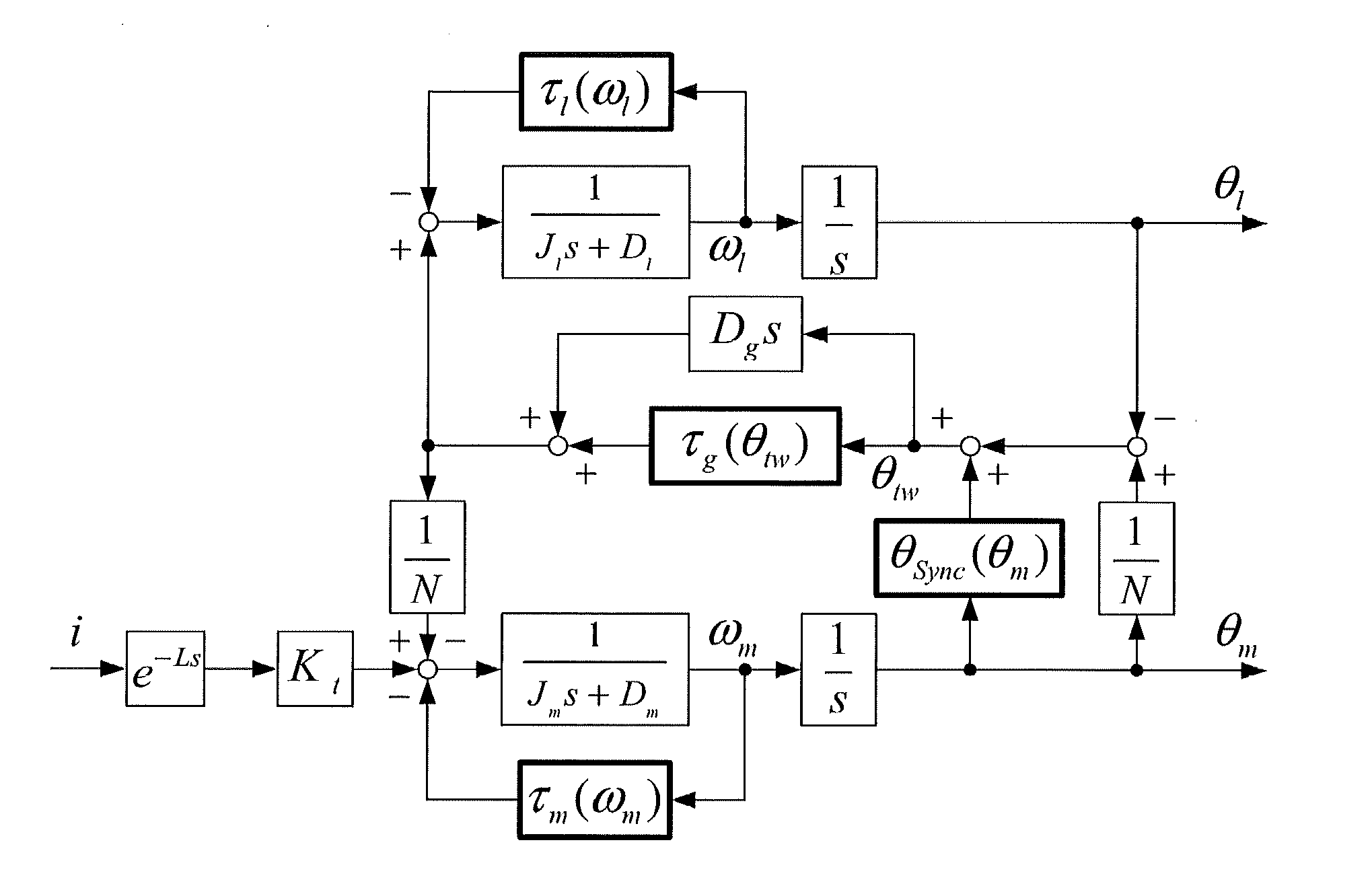
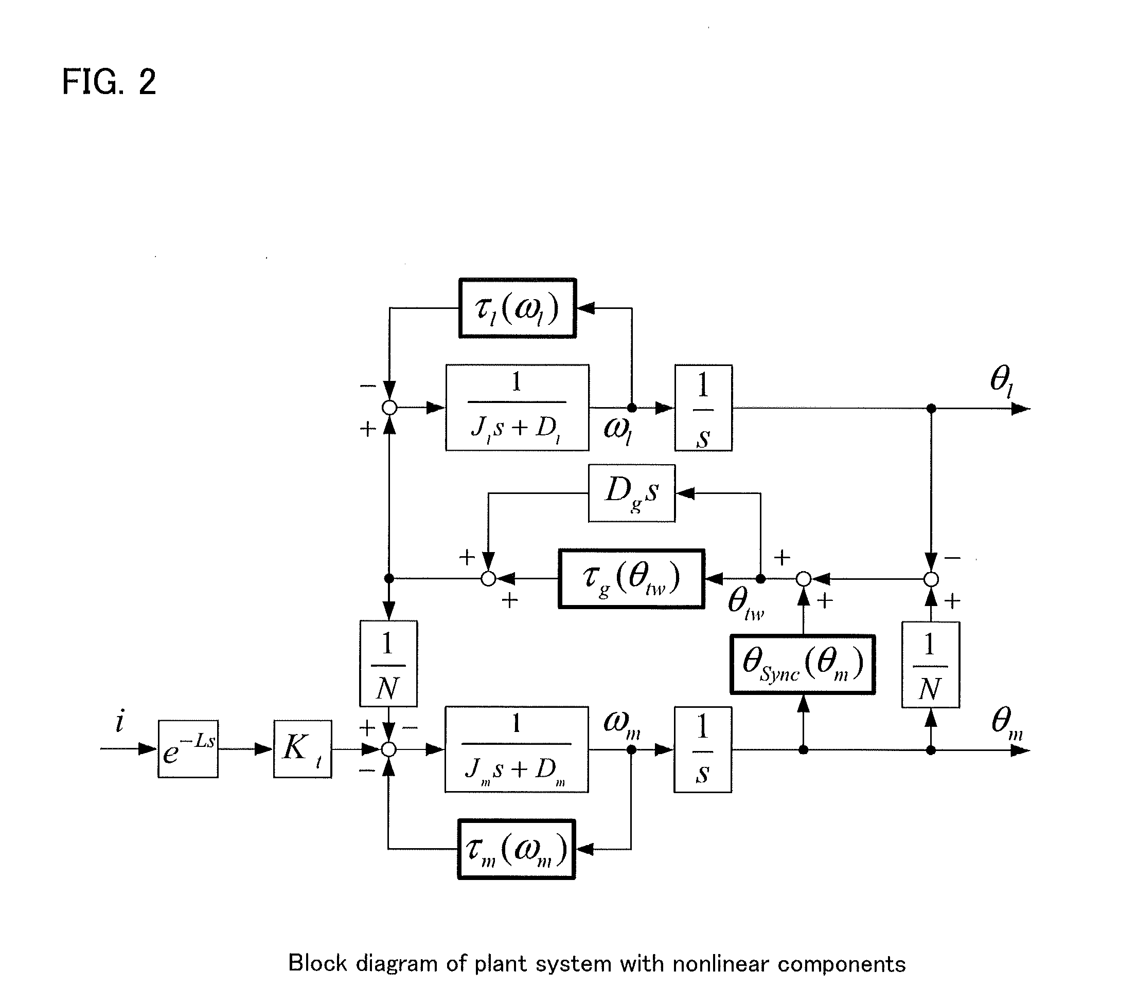
[0078]Among the nonlinear elements treated as objects to be controlled, the angular transmission errors and relative rotation-synchronous components are the causes of steady-state deviation and vibration inducement in the load position, and the gear meshing conditions of the wave gear device must therefore he taken into account when setting a positioning-feeding angle for the experiment validation. In view of this, to evaluate variation in steady-state deviation of the static load position, the evaluation is made according to the feed angle whereby the meshing of the gears changes, so that the stabilized relative rotation-synchronous comp...


PUM


Abstract

A positioning control system for an actuator provided with a strain wave gearing is provided with: a semi-closed feedback controller FB(s) that controls a load shaft position θl on the basis of a feedback motor shaft position θm; and a feedforward linearization compensator configured by incorporating a nonlinear plant model for an object to be controlled into a feedback linearization compensator using an exact linearization technique. The feedforward linearization compensator uses a forward-calculated state quantity estimated value x* to calculate a feedforward current instruction i*ref and a feedforward motor position instruction θ*m to be input into the feedback controller FB(s). A positioning error caused by a non-linear element (non-linear spring property, relative rotational synchronization component, and non-linear friction) of the strain wave gearing is compensated for by the feedforward linearization compensator.

Description

TECHNICAL FIELD[0001]The present invention relates to a positioning control system for an actuator for reducing rotational output of a motor via a wave gear device and outputting the reduced output from a load shaft. More specifically, the present invention relates to a positioning control system for an actuator provided with a wave gear device, designed so that an exact linearization method can be used to suppress the loss of positioning control precision for a load shaft due to nonlinear spring characteristics, relative rotation-synchronous components, and nonlinear friction of the wave gear device.BACKGROUND ART[0002]Certain actuators use a wave gear device as a reducer for reducing and outputting the rotation of a motor. A known example of a controller for controlling the positioning of an actuator of this configuration is a semi-closed loop control system in which the rotational position and rotational speed of a motor shall are detected by an encoder attached to the motor shal...

Claims


Application Information

Patent Timeline
Patent Type & Authority Applications(United States)
IPC IPC(8): G05B5/00
CPCG05B5/00F16H49/001G05B2219/49292H02P23/00
Inventor YAMAMOTO, MASAFUMIOKITSU, YOSHIFUMIIWASAKI, MAKOTO
Owner HARMONIC DRIVE SYST IND CO LTD
Why Eureka
Try Eureka