Antenna module and method for manufacturing the same

Inactive Publication Date: 2014-07-24
NITTO DENKO CORP
View PDF0 Cites 7 Cited by
  • Summary
  • Abstract
  • Description
  • Claims
  • Application Information

AI Technical Summary

Benefits of technology

[0028]In this case, the first portion and the fourth portion of the dielectric film can be reliably fixed to the support body while the effect of the relative permittivity of the support body on the received or transmitted electromagnetic wave is reduced.
[0

Problems solved by technology

Degree of freedom in arranging the terahertz oscillation device is limited due to a decrease in size and thickness of the electronic apparatuses.
Therefore, it is difficult to

Method used


Image

  • Antenna module and method for manufacturing the same
  • Antenna module and method for manufacturing the same
  • Antenna module and method for manufacturing the same

Examples


Example

(1) First Embodiment

(1-1) Configuration of Antenna Module

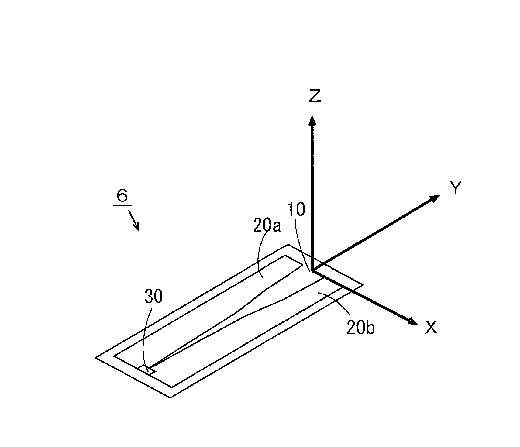
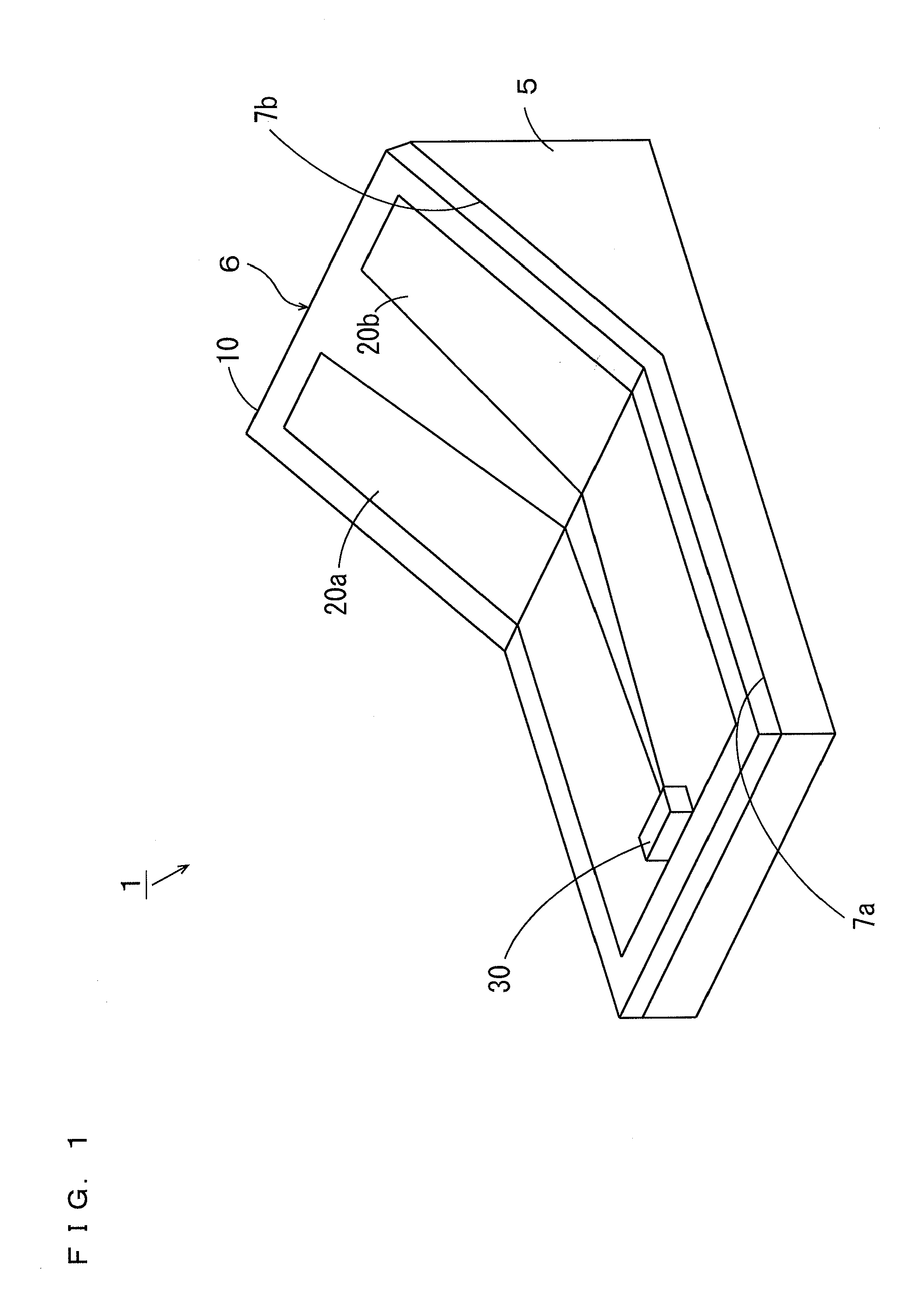
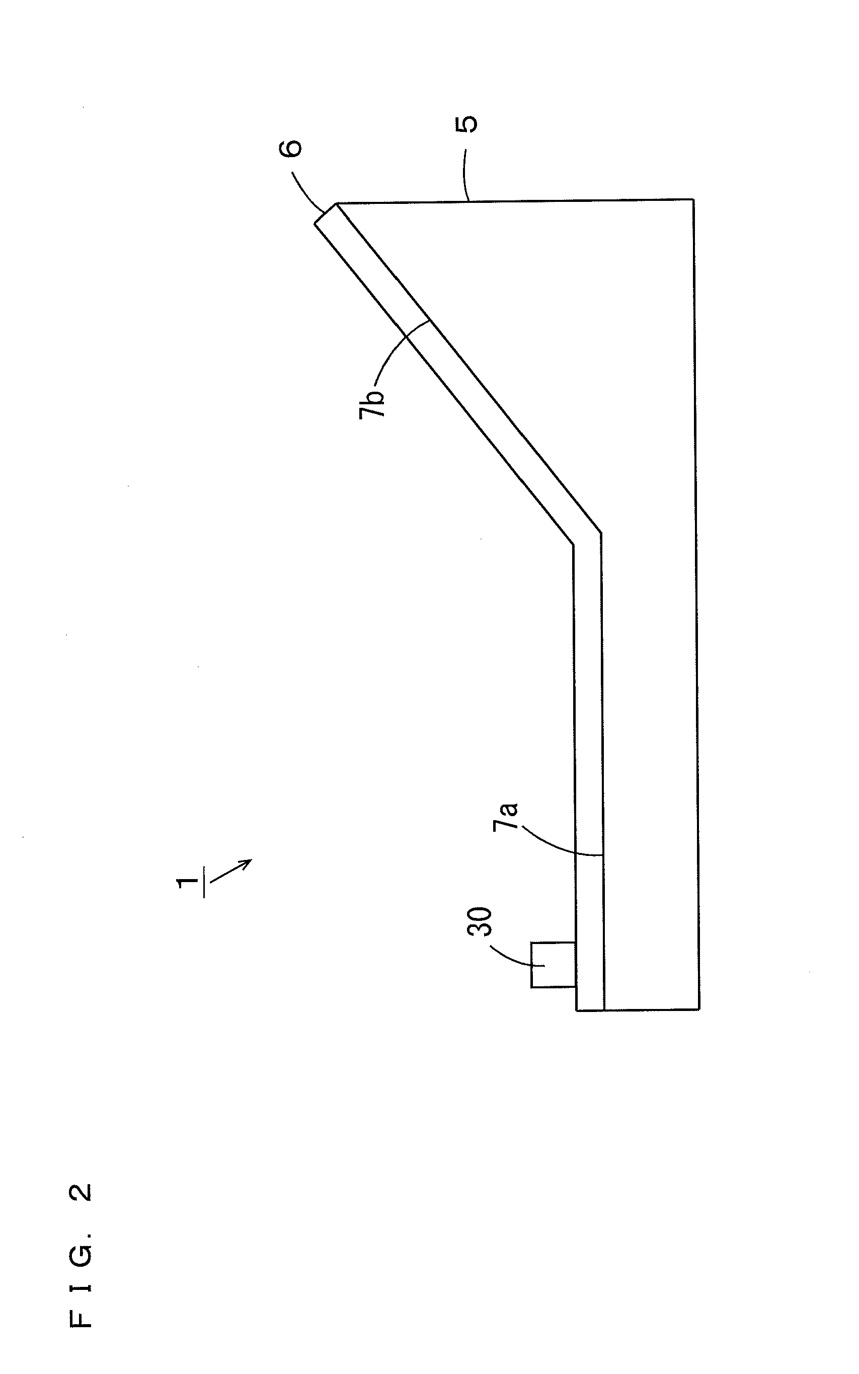
[0085]FIG. 1 is an external perspective view of the antenna module according to the first embodiment of the present invention. FIG. 2 is a schematic side view of the antenna module of FIG. 1.

[0086]In FIG. 1, the antenna module 1 includes a support body 5 and an antenna body 6. For example, polytetrafluoroethylene (PTFE), FR4 (glass epoxy) or porous PTFE which is a porous media of PTFE is used as material for the support body 5. The support body 5 preferably has a relative permittivity of not more than 3.0, and more preferably has a relative permittivity of not more than 2.0, in a used frequency within the terahertz band. FR4 has a relative permittivity of 4.2 in the terahertz band, and PTFE has a relative permittivity of 2.0 in the terahertz band.

[0087]The support body 5 has a flat support surface 7a and a support surface 7b that extends obliquely upward from one side of the support surface 7a. The support surface 7a is an exa...

Example

(2) Second Embodiment

[0141]FIG. 18 is an external perspective view of the antenna module according to the second embodiment of the present invention. FIG. 19 is a schematic side view of the antenna module of FIG. 18. Regarding an antenna module 1a of FIGS. 18 and 19, difference from the antenna module 1 of FIGS. 1 and 2 will be described.

[0142]The antenna module 1a of FIGS. 18 and 19 includes a rectangular parallelepiped support body 15 instead of the support body 5 of FIGS. 1 and 2. The antenna body 6 is attached to one surface 15a of the support body 15 and the other surface 15b parallel to the one surface 15a while being bent in a U-shape. The one surface 15a of the support body 15 is an example of a third surface of claim 2, and the other surface 15b is an example of a fourth surface of claim 4. A portion of the dielectric film 10 attached to the one surface 15a of the support body 15 is an example of a first portion of claim 2, and a portion of the dielectric film 10 attached t...

Example

(3) Third Embodiment

[0153]FIG. 25 is an external perspective view of the antenna module according to the third embodiment of the present invention. FIG. 26 is a schematic side view of the antenna module of FIG. 25. Regarding the antenna module 1b of FIGS. 25 and 26, difference from the antenna module 1 of FIGS. 1 and 2 will be described.

[0154]The antenna module 1b of FIGS. 25 and 26 includes a plate-shaped support body 25 instead of the support body 5 of FIGS. 1 and 2. The dielectric film 10 of the antenna body 6 includes portions R1, R2, R3, R4 that are arranged from the one end to the other end. The portion R1 is an example of a first portion of claim 2, the portion R2 is an example of a second portion of claim 2, the portion R3 is an example of a third portion of claim 7 and the portion R4 is an example of a fourth portion of claim 7. The pair of electrodes 20a, 20b and the semiconductor device 30 are provided on the main surface of the portion R2 of the dielectric film 10. An an...


PUM

PropertyMeasurementUnit
Dielectric polarization enthalpyaaaaaaaaaa
Angleaaaaaaaaaa

Abstract

An antenna module includes a support body and an antenna body. The support body has a flat support surface and a support surface that extends obliquely upward from one side of the support surface. The antenna body is attached to the support surface while being bent along the support surface of the support body. The antenna body is constituted by a dielectric film, a pair of electrodes and a semiconductor device. The pair of electrodes is formed on a main surface of the dielectric film, and the semiconductor device is mounted on the end of the electrode.

Description

BACKGROUND OF THE INVENTION[0001]1. Field of the Invention[0002]The present invention relates to an antenna module that transmits or receives an electromagnetic wave of a frequency in a terahertz band not less than 0.05 THz and not more than 10 THz, for example, and a method for manufacturing the antenna module.[0003]2. Description of Related Art[0004]Terahertz transmission using an electromagnetic wave in the terahertz band is expected to be applied to various purposes such as short-range super high speed communication and uncompressed delayless super high-definition video transmission.[0005]A terahertz oscillation device using a semiconductor substrate is described in JP 2010-57161 A. In the terahertz oscillation device described in JP 2010-57161 A, first and second electrodes, an MIM (Metal Insulator Metal) reflector, a resonator and an active element are formed on the semiconductor substrate. A horn opening is arranged between the first electrode and the second electrode.BRIEF S...

Claims


Application Information

Patent Timeline
IPC IPC(8): H01Q3/01
CPCH01Q3/01H01Q1/38H01Q13/085H01Q21/28Y10T29/49018
Inventor HODONO, MASAYUKIINOUE, MASAMIHONJO, MITSURU
Owner NITTO DENKO CORP
Why Eureka
Try Eureka