Li-ion pouch cell and a cell module

a technology of cell module and pouch cell, which is applied in the field of pouch cell and cell module, can solve the problems of major decrease in cell energy density, difficult to quickly remove heat, and low energy density of pouch cell, so as to reduce the ability to thermally control, reduce the difference in cell temperature, and accelerate the effect of cell cooling

Active Publication Date: 2014-07-24
FARASIS ENERGY
View PDF6 Cites 11 Cited by
  • Summary
  • Abstract
  • Description
  • Claims
  • Application Information

AI Technical Summary

Benefits of technology

[0017]The Li-ion pouch cell and the cell module according to the present application could increase the capability to thermally control the pouch cell temperature, minimize differences in cell temperature, monitor internal cell temperature, cool the cell rapidly, and increase cell and module safety by providing a thermally conductive pathway from the internal electrode stack to the outside of the pouch cell by way of thermally conductive extensions, extending beyond the electrode stack and contained fully within the sealed pouch cell. The invention could enable improved cell and module thermal management without the need for additional elements to pass through the pouch cell seal, allowing for minimal impact on cell energy density, performance or life and difficulty of manufacturing. The Li-ion pouch cell and the cell module according to the present application could provide greater thermal control and safety and could be widely used in battery production.

Problems solved by technology

Li-ion pouch cells provide very high energy density but can suffer from degradation due to excessive or non-uniform heating of the electrode stack, particularly for thicker cells.
Also in a rapid thermal event, it is often very difficult to remove the heat quickly enough to prevent thermal runaway and related safety issues.
However, these solutions to addressing thermal management and control in Li-ion battery applications can lead to a major decrease in the cell energy density because of the extra volume and weight of the tabs or cooling plates or the increase in the number of thinner, lower capacity or lower impedance cells required to meet the energy demands of an application.
These solutions can also lead to additional cost of the overall battery system.
It is also well known that it is difficult and expensive to increase the size or number of tabs or other thermally conductive elements passing through the Aluminum laminate packaging seal due to manufacturing complications and the increasing likelihood of leaks forming around the area where the tab passes through the seal.
The cells become more susceptible to failure as the number and size of elements, such as tabs, passing through the pouch cell seal is increased.

Method used


Image

  • Li-ion pouch cell and a cell module
  • Li-ion pouch cell and a cell module
  • Li-ion pouch cell and a cell module

Examples


example 1

Construction and performance of a 10 Ah Li-ion Pouch Cell with Internal Thermally Conductive Extensions

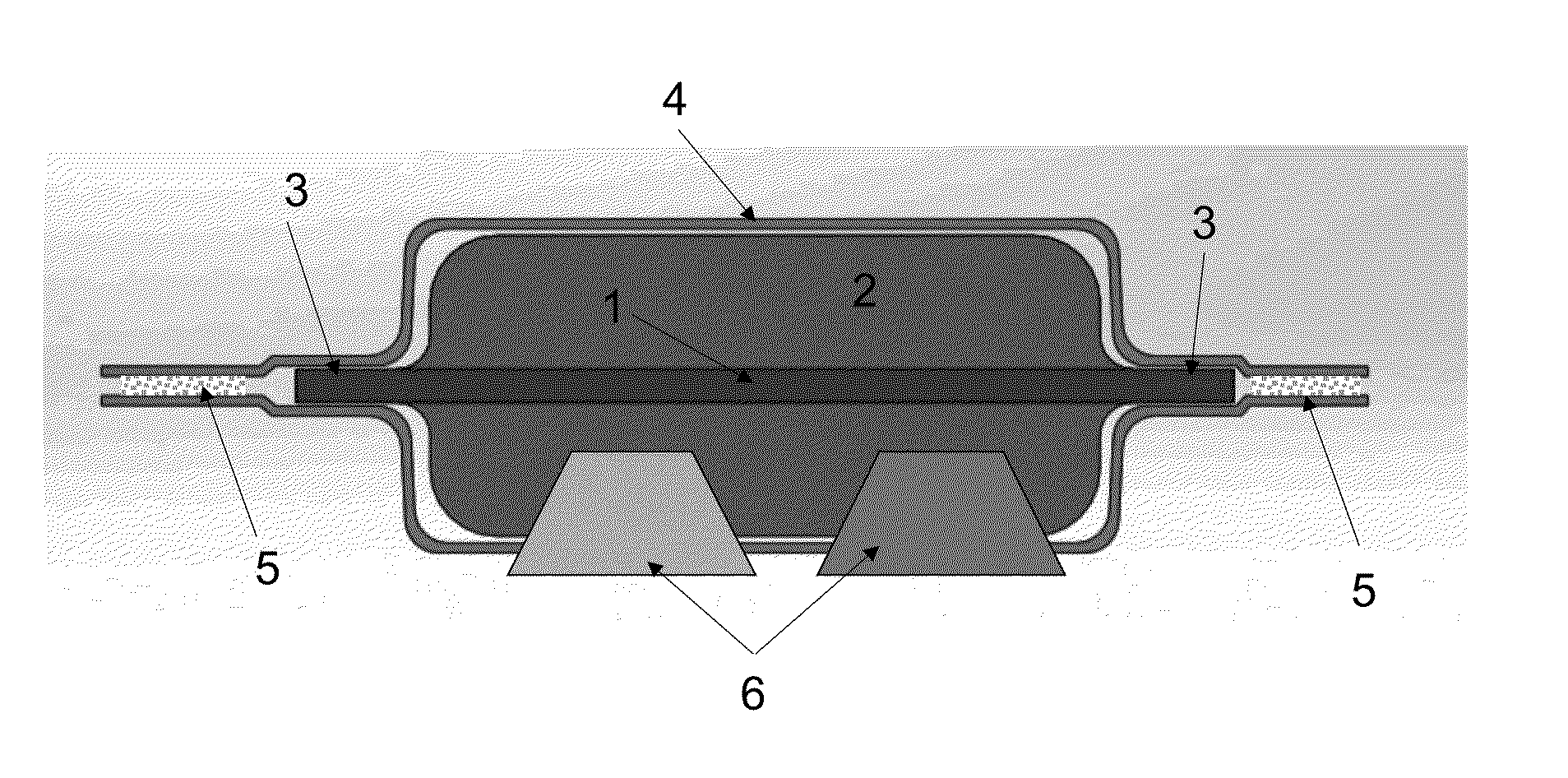
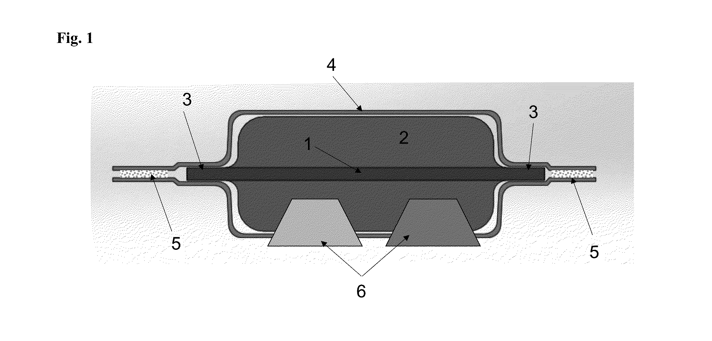
[0052]In this example a Li-ion pouch cell of this invention was built. The cathode electrodes were prepared by conventional methods using conventional Li-ion battery materials. The cathode current collector was Al-foil which was coated with a laminate slurry of Li(NiCoMn)O2 or NCM(111) active material, carbon based conductive additive and PVDF binder. Once dry the cathode electrodes were calendared. The anode electrodes were prepared by coating a copper foil current collector with a laminate slurry of graphitic carbon and PVDF binder. Once dry the anode electrodes were calendared. FIGS. 4A) and 5A) show illustrations of the standard cathode and anode electrodes respectively when prepped for cell assembly. The bare foil region at the top of the electrode 1 was used to connect the electrodes 1 to the electrical tabs 6. FIGS. 4B) and 5B) show cathode and anode electrodes respectively ...

example 2

Cooling a 10 Ah Li-ion Pouch Cell with Internal Thermally Conductive Extensions

[0055]In this example the cell of Example 1 was discharged at a ˜2 C rate (20 A) with and without utilizing the thermal extensions to cool the cell while the cell temperature at the face of the cell and at the anode tab 6 of the cell was monitored. Thermocouples were attached to the middle of the face of one side of the cell (D) and to the anode tab (C) of the cell to continuously monitor the cell temperature during cycling. The anode tab temperature provides an indication of the internal temperature of the cell since the anode tab provides a direct thermal connection to the electrode stack 2, and the cell face provides an indication of the overall cell temperature. FIG. 8 A) shows an image of the cell and the location of the thermocouples at the face of the cell (D) and the anode tab of the cell (C).

[0056]For the first test the cell was placed on a thermally insulating surface. No external cooling was us...


PUM

PropertyMeasurementUnit
charge rateaaaaaaaaaa
temperatureaaaaaaaaaa

Abstract

The present invention provides a Li-ion pouch cell wherein the Li-ion pouch cells comprise a sealed enclosure, electrode stack and thermally conductive elements, wherein the electrode stack and the thermally conductive elements are in the sealed enclosure, the thermally conductive elements include extensions which extend beyond the electrode stack, the sealed enclosure has thermal conductivity, the thermally conductive elements provide a thermally conductive pathway connecting the electrode stack and the sealed enclosure by way of the extension. The present invention also provides a cell module comprising the Li-ion pouch cells. The Li-ion pouch cell and the cell module according to the present application could minimize differences in cell temperature, monitor internal cell temperature, cool the cell rapidly, increase cell and module safety, allowing for minimal impact on cell energy density, performance or life and difficulty of manufacturing.

Description

CROSS-REFERENCE TO RELATED APPLICATIONS[0001]The present application claims the benefit of the United States provisional patent application No. 61 / 756,410, filed on Jan. 24, 2013 and United States provisional patent application No. 61 / 806,039, filed Mar. 28, 2013, and the contents of both provisional patent applications are incorporated by reference.GOVERNMENT LICENSE RIGHTS[0002]This invention was made in part with government support under support of the United States Government Department of Energy, ARPA-E grant number DE-AR0000270. The U.S. Government has certain rights in the invention.FIELD OF THE INVENTION[0003]The invention relates to a Li-ion pouch cell, and a cell module which comprises the Li-ion pouch cells.BACKGROUND OF THE INVENTION[0004]Li-ion pouch cells provide very high energy density but can suffer from degradation due to excessive or non-uniform heating of the electrode stack, particularly for thicker cells. For example, very thick cells when discharged at high ra...

Claims


Application Information

Patent Timeline
Patent Type & Authority Applications(United States)
IPC IPC(8): H01M10/60
CPCH01M10/50H01M10/052H01M10/058H01M10/613H01M10/647H01M10/654H01M10/655H01M10/658Y02E60/10Y02P70/50
Inventor KEPLER, KEITH D.VERMEULEN, ROBBERTHAILEY, PHILLIPLARSON, ANDREW
Owner FARASIS ENERGY
Why Eureka
Try Eureka