Protein microarray assay imager

a protein microarray and imager technology, applied in the direction of material analysis using wave/particle radiation, fluorescence/phosphorescence, instruments, etc., can solve the problems of inability to adjust the settings of instruments to optimize, the best performing instruments are expensive, and the device is bulky and not easily accessible to remote handling, etc., to achieve high-performance microarray scanning, reduce capital investment, and increase protein binding capacity

Active Publication Date: 2014-07-24
GRACE BIO-LABS
View PDF7 Cites 16 Cited by
  • Summary
  • Abstract
  • Description
  • Claims
  • Application Information

AI Technical Summary

Benefits of technology

[0006]The inventors herein have recognized that by using porous nitrocellulose in conjunction with quantum nanoparticle fluorophores in microarray systems, the detection sensitivity of the assays can be improved while also permitting the development of more efficient, yet more compact and cost-effective instruments. In particular, by using porous nitrocellulose as a microarray assay substrate, the high binding capacity and enhanced internal scattering properties of porous nitrocellulose can be leveraged to provide a higher level of emitted light. Consequently, imaging can be performed using single source lasers and digital cameras (such as CCD cameras) to stimulate the fluorophores. Overall, the cost of microarray imaging is reduced. In addition, the instrumentation can be made cheaper and more compact. Further still, the combination may be couplable to robotic fluid handling assay systems, enabling remote imaging and analysis. The inventors have further recognized that by using a camera for imaging, various dithering algorithms may be developed to increase the resolution of captured images during the acquisition or as a post-acquisition process. As such, this improves image analysis while also reducing the need for reiterating scans.
[0020]Although the above system has been described in the context of bright fluorophores, the system could also be used with organic fluorophores in the instances where there is a substantial amount of analyte to be detected and the full sensitivity of the system is not required. In these cases, the system still offers the advantages of economy, size, and ease of use.

Problems solved by technology

For example, the instruments that perform the best can be very expensive.
In addition, the devices tend to be bulky and not easily amenable to remote handling.
Another issue with the scanning devices is that the instrument settings need be adjusted to optimized without which the microarray images can be either saturated (that is, too much signal) or not detectable at all (that is, too little signal).
Given that a single scan can take up to several minutes to complete, this iterative process can become very time consuming and inefficient.

Method used


Image

  • Protein microarray assay imager
  • Protein microarray assay imager
  • Protein microarray assay imager

Examples


embodiment 600

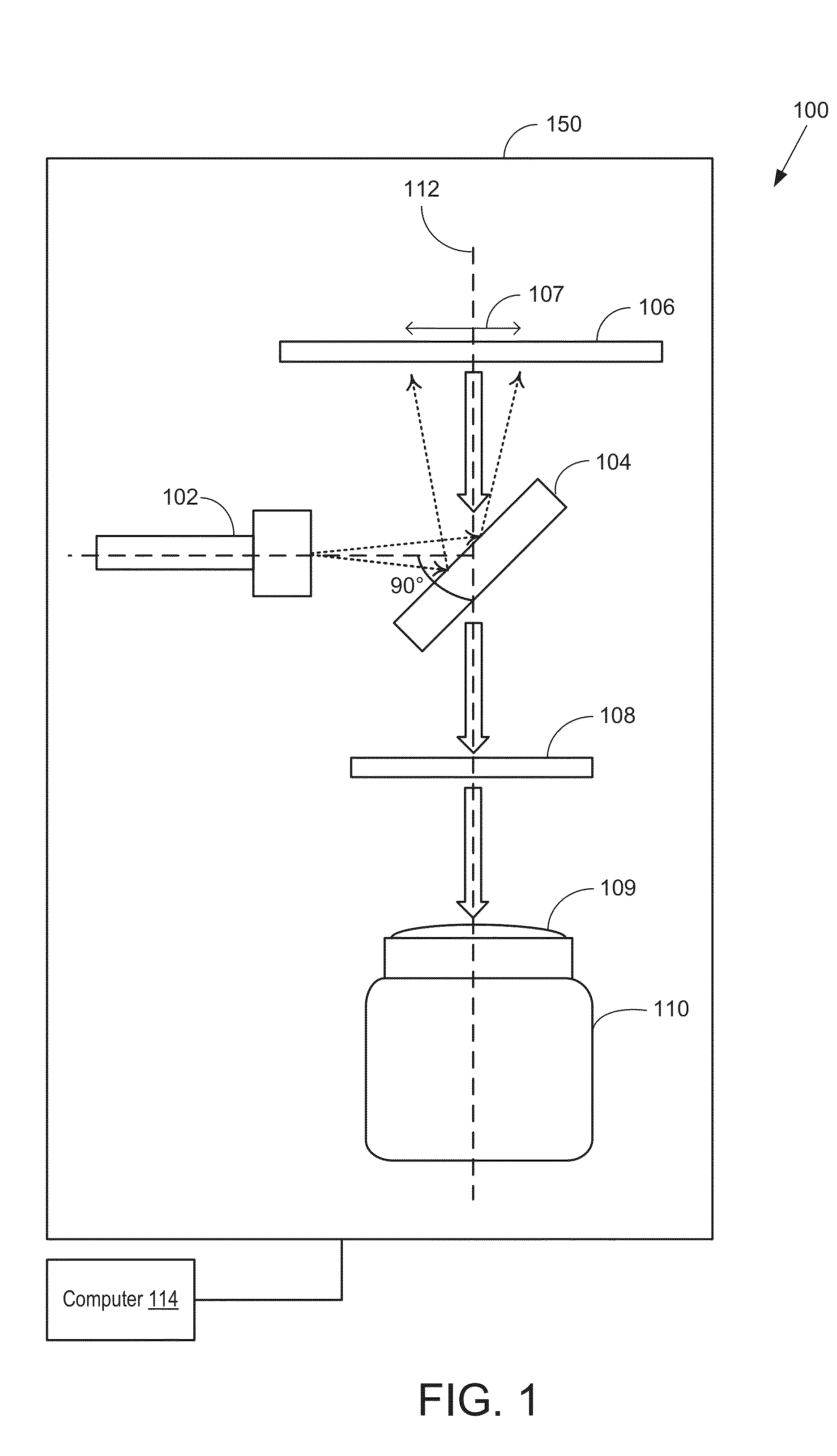
[0162]The imager of the present disclosure may adopt several configurations and component arrangements. An example detailed embodiment 600 of an imager (such as the imager of FIG. 1) suited for single-side imaging is shown in FIG. 6. The configuration of the imager of FIG. 6 matches the configuration shown schematically in FIG. 1 in orientation and component alignment.

[0163]Imager 600 includes a frame 605 to which the various optical components are coupled. The components may be arranged at various levels or stacks. Each level arranged perpendicular to a longitudinal axis of frame 605. In one example, frame 605 may be sized to fit imager 600 is a standard imaging chamber. Frame 605 includes vertically arranged supporting rods 625a-b connected via cross beam 626. While the depicted example shows two supporting rods (a distal rod 625b and a proximal rod 625a), any number of supporting rods may be present. In one example, cross beam 626 may be coupled to the supporting rods at a mid-he...

second embodiment

[0183]In the imaging device pictured in FIG. 7, the acquisition head 706 may be attached to a mounting frame 715. The mounting frame may comprise two upright arms 716. The upright arms may provide a vertical point to affix components of the imagine device. Spanning the upright arms 716 may be a horizontal cross beam 717. The horizontal cross beam 717 may be attached on to the upright arms 716 by fasteners 721. In alternate embodiments, a mounting frame may comprise a single integrated component, for example a molded mounting frame.

[0184]The frame may be further bolted within an enclosure or housing (not shown). Attachment points on the base 720 of the mounting frame may be used to attach or secure the mounting frame, and components of the imaging device therein to an external housing. In one example, the base may comprise a metallic plate with regularly spaced threaded holes. The threaded holes suitable for attaching the upright arms 716, or for attaching a base 720 of the mounting ...


PUM

PropertyMeasurementUnit
thickaaaaaaaaaa
thickaaaaaaaaaa
thickaaaaaaaaaa

Abstract

An approach is described that combines distinct properties of a specialized porous nitrocellulose film (PNC) with quantum nanoparticles to create an improved assay and detection sensitivity, permitting the development of a camera-based imaging system for fluorescent detection of macromolecules in microarray format. The two properties of PNC that facilitate the approach are an extraordinarily high binding capacity and a newly observed internal scattering of light. Quantum nanoparticles complement these PNC properties by providing a higher level of emitted light than the fluorescent dyes in common microarray use. Overall, the approach allows for instrument cost savings, reduced imaging time, and the ability to remotely image.

Description

CROSS REFERENCE TO RELATED APPLICATIONS[0001]The present application claims priority to U.S. Provisional Patent Application No. 61 / 756,392, filed on Jan. 24, 2013, and U.S. Provisional Patent Application No. 61 / 901,354 filed Nov. 7, 2013, the entire contents of each of which are hereby incorporated by reference for all purposes.FIELD[0002]The present application relates to methods and systems for imaging microarray data, such as protein microarray data.BACKGROUND AND SUMMARY[0003]Many methods have been developed for the detection of analytes, such as proteins, using microarrays. One widely used method is fluorescence scanning. In this technique, labels, such as fluorescent dyes (also known as organic fluorophores) are conjugated to markers within each microarray spot on an assay surface during an assay. The assay surface may be a mechanical planar surface, such as a microscope slide, a microarray channel, a microarray well, etc. For example, organic fluorophores may be conjugated to...

Claims


Application Information

Patent Timeline
Patent Type & Authority Applications(United States)
IPC IPC(8): G01N21/64
CPCG01N21/6486G01N21/6452G01N21/6458G01N21/6428G01N2223/421G01N2223/413G01N2223/401G01N21/6456B82Y15/00G01N2223/40
Inventor GRUDZIEN, JENNIPHER LYNSHULTZ, MICHAEL ALBERTBELL, FLORIAN GENEMCGRATH, CHARLES M.
Owner GRACE BIO-LABS
Why Eureka
Try Eureka