

Fan assembly
- Summary
- Abstract
- Description
- Claims
- Application Information
AI Technical Summary
Benefits of technology
Problems solved by technology
Method used
Image

Examples
Embodiment Construction
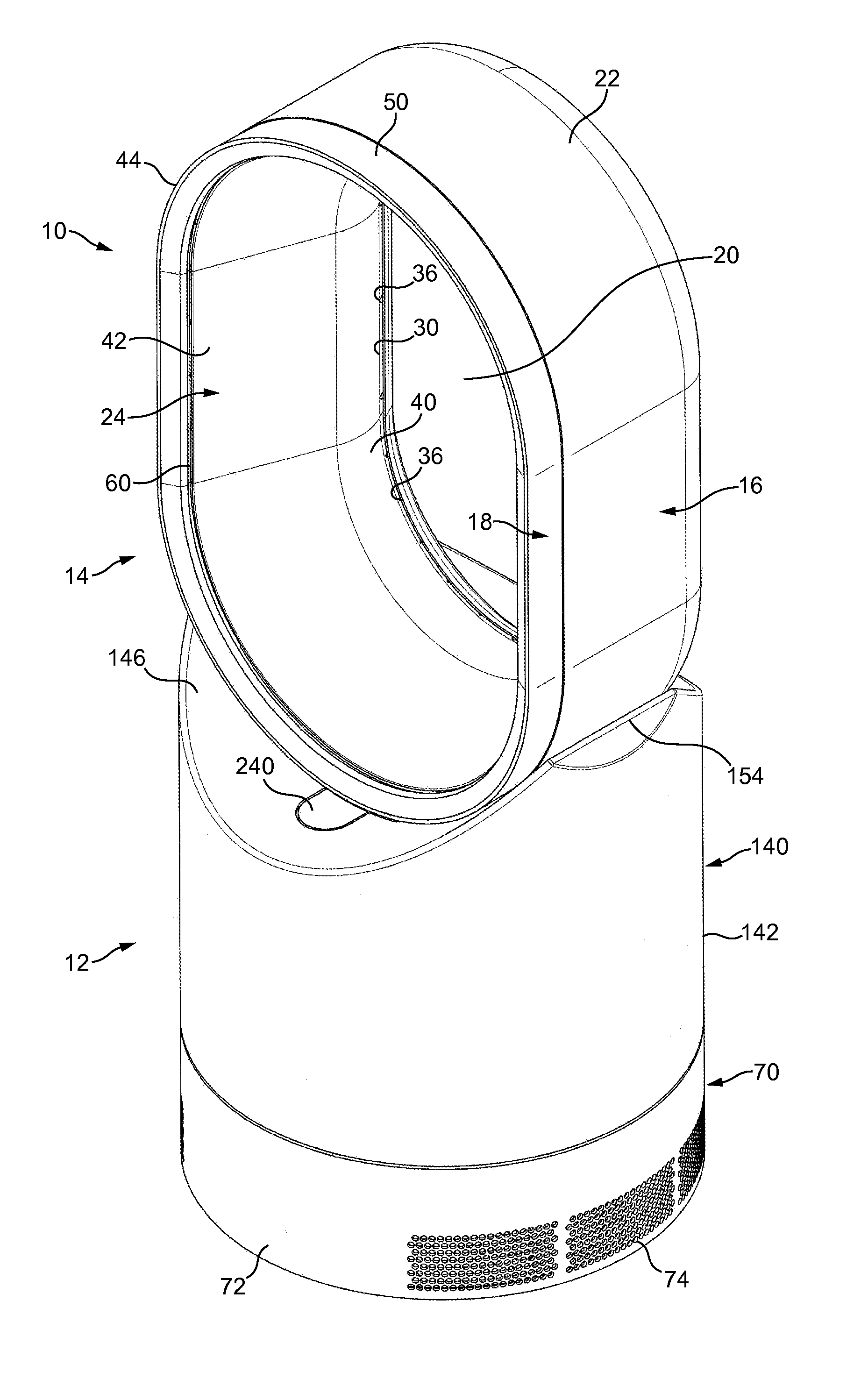
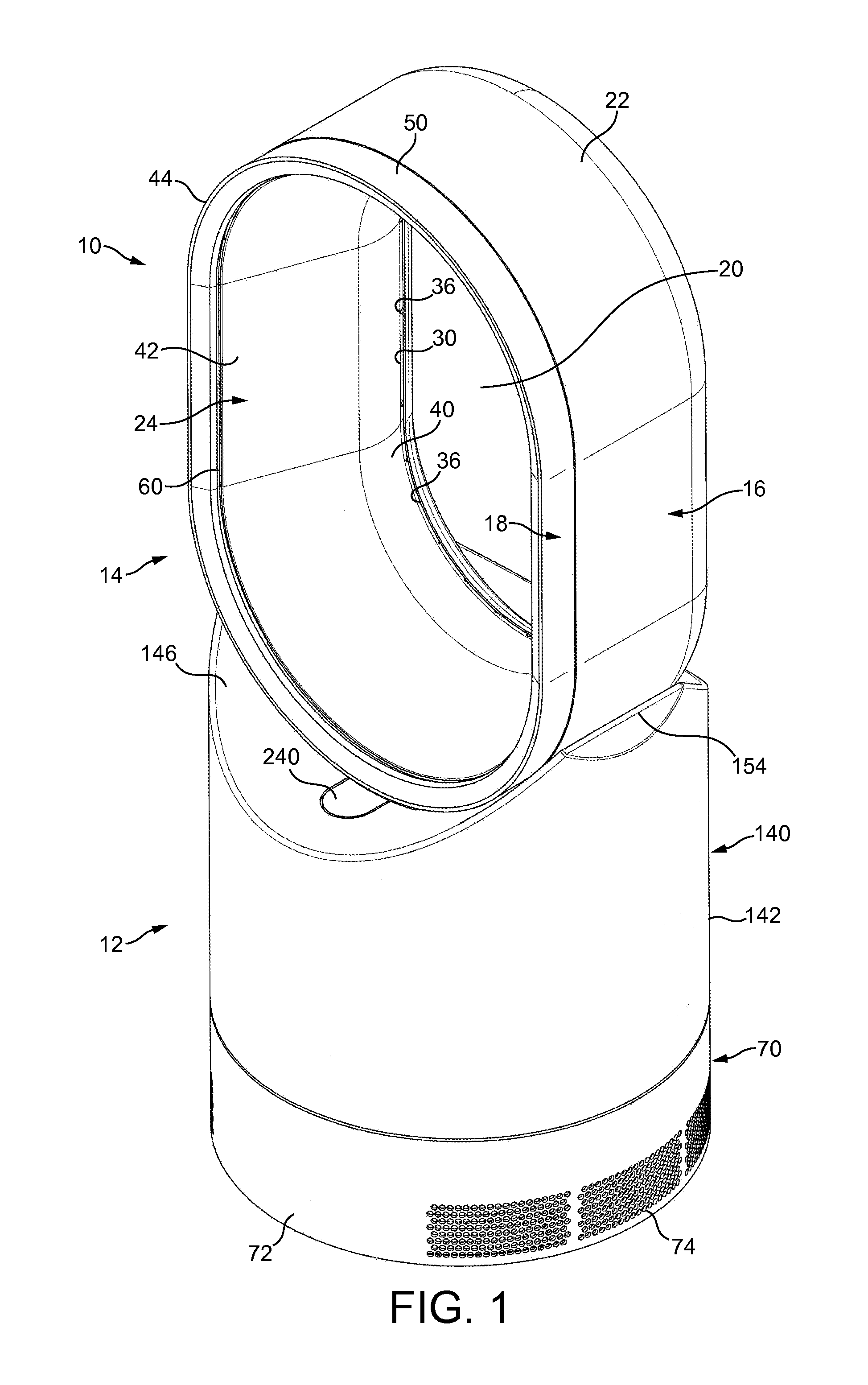
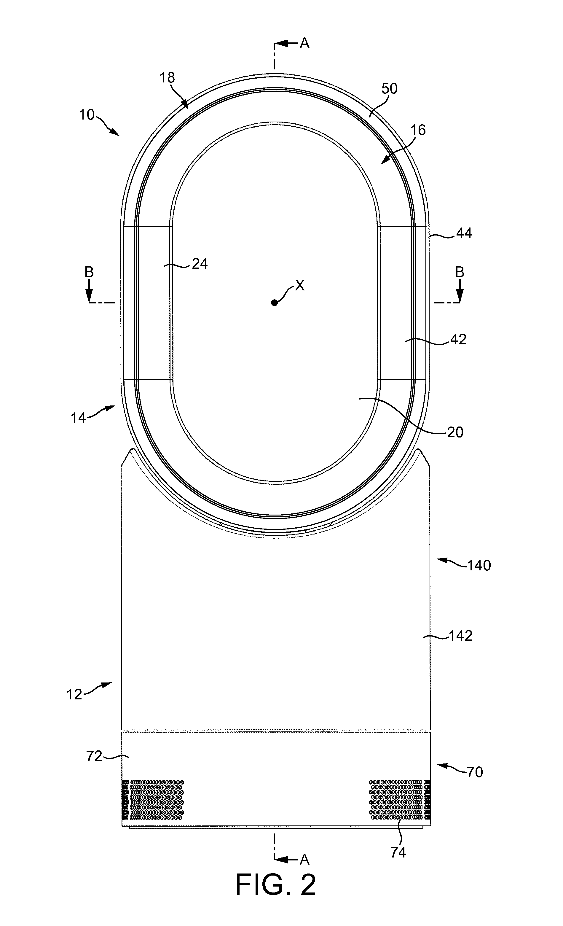
[0067]FIGS. 1 to 4 are external views of a fan assembly. In this example, the fan assembly is in the form of a humidifying apparatus 10. In overview, the humidifying apparatus 10 comprises a body 12 comprising an air inlet through which air enters the humidifying apparatus 10, and a nozzle 14 in the form of an annular casing mounted on the body 12, and which comprises a plurality of air outlets for emitting air from the humidifying apparatus 10.
[0068]The nozzle 14 is arranged to emit two different air flows. The nozzle 14 comprises a rear section 16 and a front section 18 connected to the rear section 16. Each section 16, 18 is annular in shape, and extends about a bore 20 of the nozzle 14. The bore 20 extends centrally through the nozzle 14 so that the centre of each section 16, 18 is located on the axis X of the bore 20.
[0069]In this example, each section 16, 18 has a “racetrack” shape, in that each section 16, 18 comprises two, generally straight sections located on opposite side...
PUM
| Property | Measurement | Unit |
|---|---|---|
| Time | aaaaa | aaaaa |
| Flow rate | aaaaa | aaaaa |
| Shape | aaaaa | aaaaa |
Abstract
Description
Claims
Application Information