Bicycle, Modifiable for Uphill, Downhill and/or Trail Conditions

a technology of bicycles and bikes, applied in the field of bicycles, can solve the problems of low rigidity of sprung frames, inability to provide potentially useful features in current regulating systems, and inability to optimize bicycle geometry. , to achieve the effect of maximizing bicycle geometry, minimizing the range of modifiability, and ensuring the stability

Inactive Publication Date: 2014-07-31
HUDAK BORIS
View PDF6 Cites 16 Cited by
  • Summary
  • Abstract
  • Description
  • Claims
  • Application Information

AI Technical Summary

Benefits of technology

[0021]The advantages of said bicycle are in both maintaining constant distance of a Bottom Bracket from a Rear Wheel while absorbing shocks and in capability to adjust a Rider-Positioning System and a Regulating System to conform softness of shock absorption, rider's body position and weight allocation with actual speed and with unevenness and steepness of ground.
[0022]The following versions of said bicycle enable rider to optimize bicycle geometry effectively and / or to change either softness of suspension or the range of its modifiability.
[0023]The bicycle, with a movable Pedal Assembly with an adjustable basic position, has a Hanger Unit of the Pedal Assembly, which is swivelably and slidably connected to a Frame or to a Seat Assembly or to the front end of a Tail and is lockable against sliding, by a Pedal Lock. The bicycle, with a movable Pedal Assembly and appliances for enhancing lateral rigidity, has a Tail and / or a Hanger Unit of the Pedal Assembly, which are supported against the Frame by at least one Antideviating Strut and / or Antidropping Strut. The bicycle, with a movable Pedal Assembly and with a long and\or beneficially shaped suspension travel path of Rear Wheel, has a Tail movably attached to a Frame by at least two bolts, slidable along defined sliding paths. The bicycle, with movable Seat Assembly embodied outside the room of Rear Wheel suspension travel, has a Seat Assembly equipped with either an arched Seat Post inserted into an equally curved tube of a Seat Carrier or a pair of Seat Posts inserted in a pair of tubular Seat Carriers situated on both sides of a Frame. The bicycle with a movable Handlebar Assembly has its connection firmly attached to a Fork below and above a Head Tube. The bicycle, with a shock absorbing Suspension Assembly which modifiable efficiency, is controlled by one or more Regulating Assemblies, containing either a Locking Mechanism or a Limiting Mechanism (which keeps locking of the shock absorbing function only till the critical magnitude of impact occurs) or a fluently Regulating Mechanism (which can modify wheel elevation range and suspension softness simultaneously). These assemblies interconnect a Frame with a Tail and / or the mutually slidable parts of a telescopic Fork, namely, either independently on attachment provided by a Suspension Assembly or in an arrangement, which is conjoint with a Suspension Assembly. The bicycle, with a Regulating Assembly, which modifies its overall geometry, has at least one Regulating Assembly, comprising either a Reducible Joint or a Control Mechanism attached to a Limiting Mechanism on a Fork and / or to an Expandable Joint between a Suspension Unit and a Frame or a Tail. The bicycle, comprising a modifiable Seat Assembly and / or a modifiable Pedal Assembly and / or a modifiable Handlebar Assembly and / or a shape-modifiable Tail, and / or a shape-modifiable Frame which are mutually interconnected with a Synchronizing Assembly or a Shifting Assembly is attached to them. The bicycle, with a Regulating Assembly, has a Self-Controlling Assembly, attached to a Control Mechanism of the Regulating Assembly and / or to a control of an adjustable Suspension Assembly.

Problems solved by technology

The disadvantage of the sprung Frame is in its lower rigidity.
However, the locking of suspension, on smooth roads and uphill climbing, remains lateral rigidity of bicycle non-enhanced, although typically, higher rigidity is most desired in such conditions.
Manual control of Regulating System, particularly when control unit is not situated on Handlebar, is challenging, This is especially unfavourable while riding in frequently changing trail conditions, when driving situations are demanding and when frequent softness regulation is the most desirable.
Current Regulating Systems don't provide potentially useful features like automatic switching-on of a Suspension System in response to over-limit loading, locking of Frame System in selected elevation travel position or adjusting geometry so that full squeezing of Suspension Units respects maximal elevation, predetermined according to needs.
This gives only limited options for adapting rider's centre of gravity over wheelbase to eliminate forward rollover risk while riding downhill or to prevent Front Wheel lifting while riding uphill.
Another disadvantage is inability to rise up a Bottom Bracket while riding over uneven ground or downhill trail or jumping.
Such rising would diminish the risk of pedal crank impact on ground undulations.
However, the benefits of these solutions are generally smaller than their disadvantages in poorer rigidity, weight aerodynamics, and performance, especially if these assemblies are not adjustable while riding or if standard Drive train Assembly cannot be used with them.
Therefore this solution cannot fully eliminate forward component of movement and cannot enable backwardly inclined elevation path at all.

Method used


Image

  • Bicycle, Modifiable for Uphill, Downhill and/or Trail Conditions
  • Bicycle, Modifiable for Uphill, Downhill and/or Trail Conditions
  • Bicycle, Modifiable for Uphill, Downhill and/or Trail Conditions

Examples


example 1

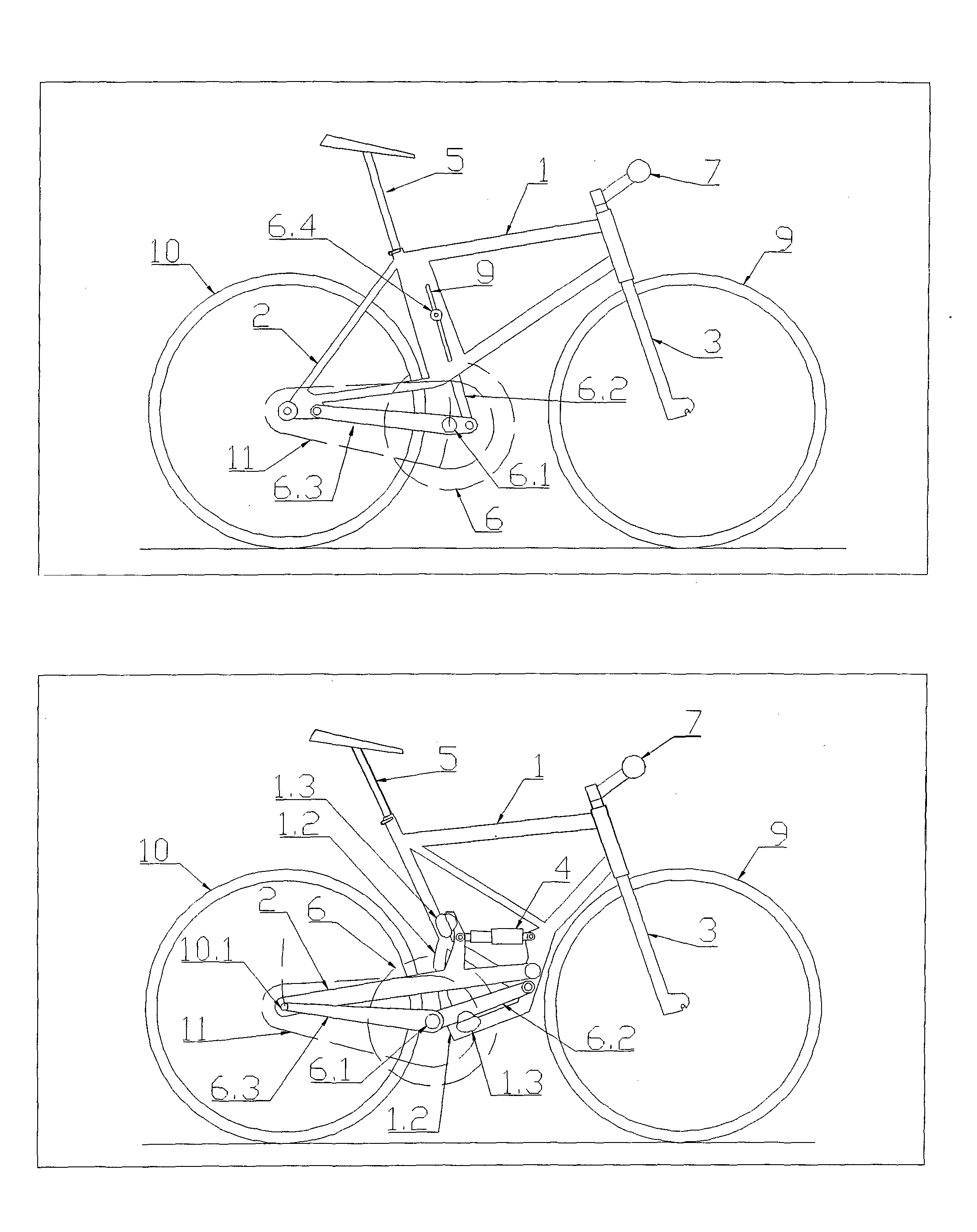
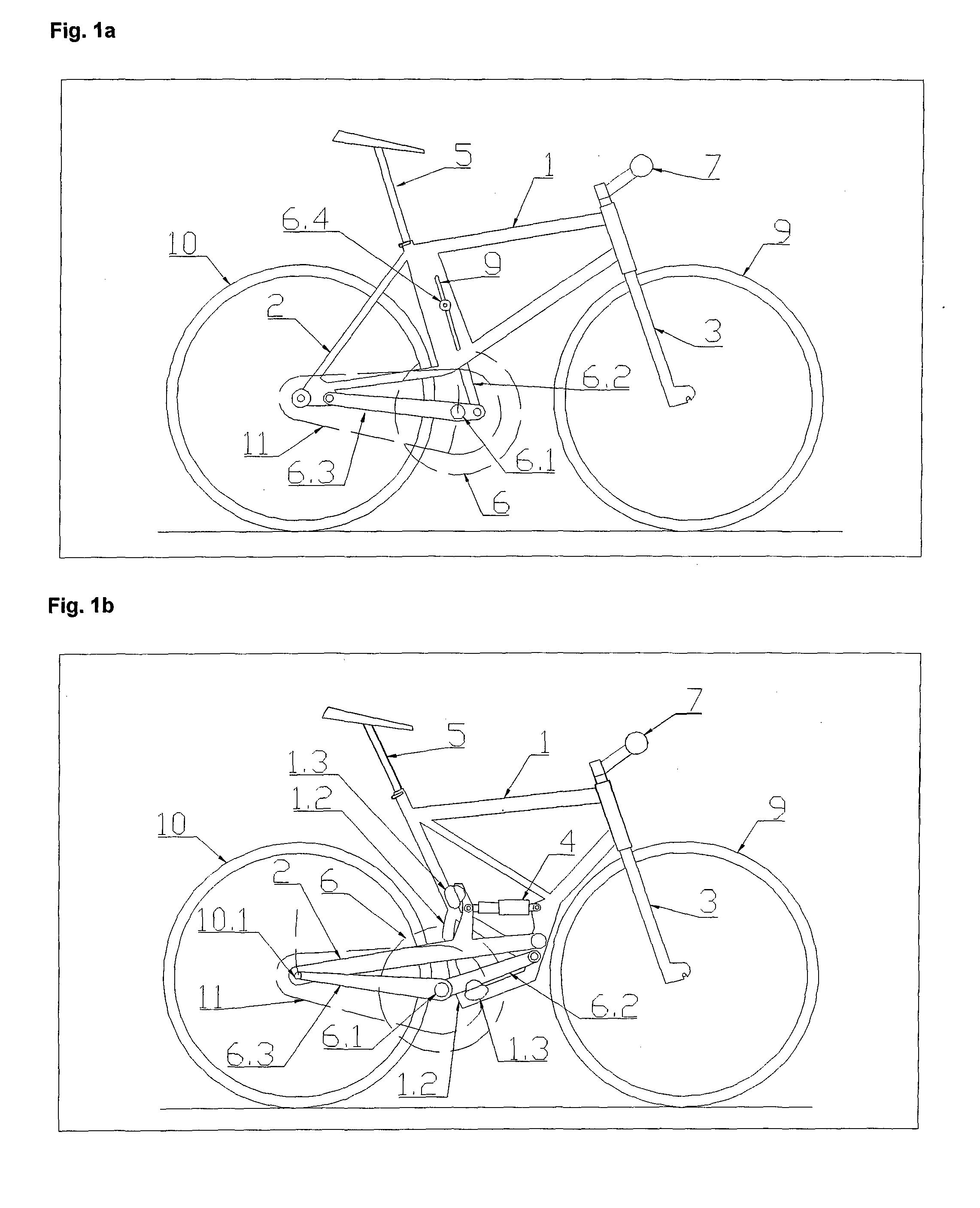
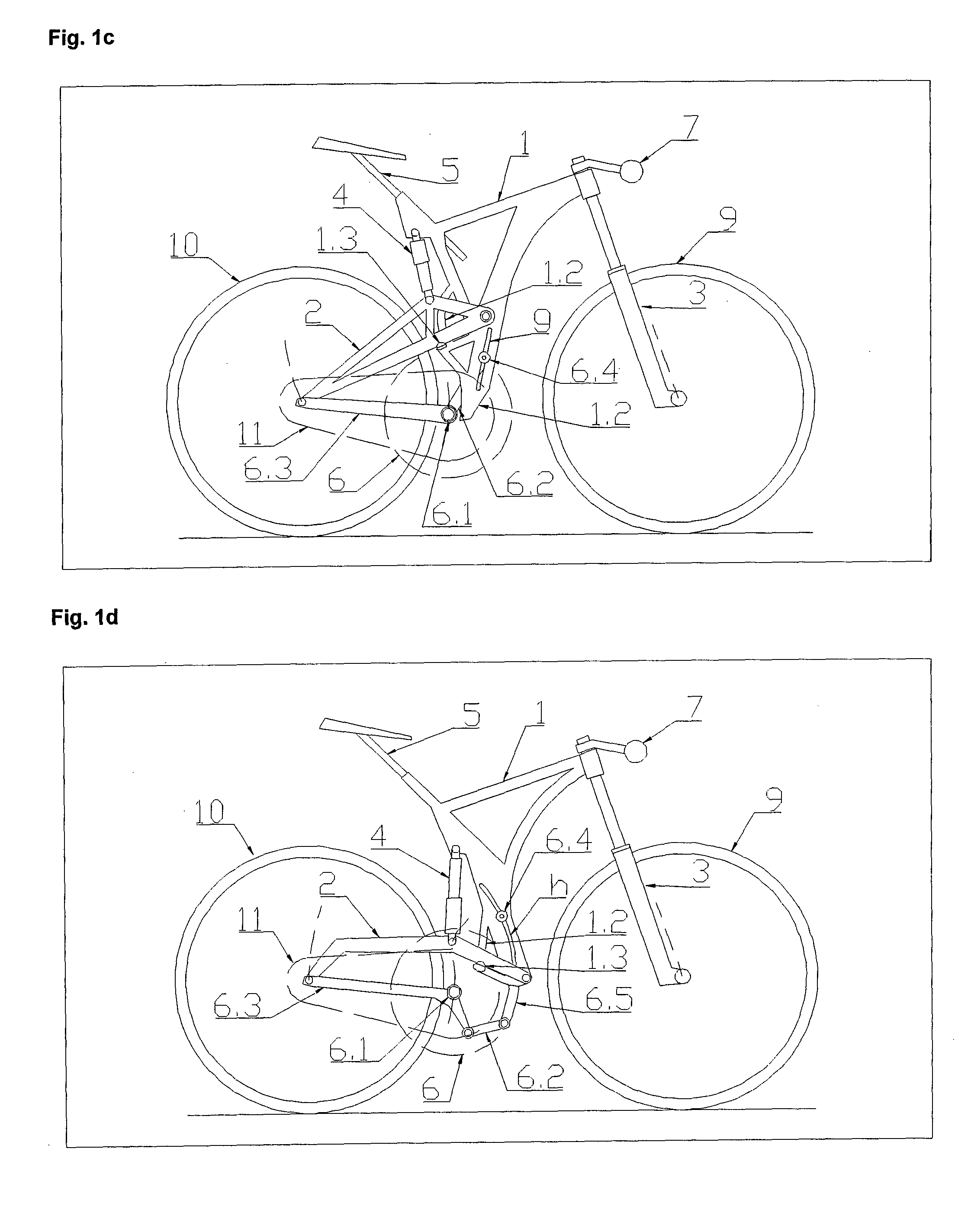
[0036]The bicycle shown on FIG. 1a to 1f comprises assemblies that co-create a Frame System, Motion System, Rider-Positioning System and in some cases also a sprung Suspension System. Said Frame System has a Frame 1, Tail 2 and Fork 3. The Fork 3 is rotatable and mounted on the front end of a Frame 1. A Tail 2 is attached to the rear end of a Frame 1. Said sprung Suspension System has one or more Suspension Assemblies 4. The rear Suspension Assembly 4 interconnects a movable Tail 2 with a Frame 1. The front Suspension Assembly 4 interconnects the mutually sliding parts of a Fork 3. Said Motion System has a Front Wheel 9, Rear Wheel 10 and Drivetrain Assembly 11 which are connected to Frame System assemblies. A Rear Wheel 10 is rotatably attached to a Tail 2. A Drivetrain Assembly 11 connects the Rear Wheel 10 with a Pedal Assembly 6. The Pedal Assembly 6 together with a Seat Assembly 5 and a Handlebar Assembly 7 co-creates the said Rider-Positioning System and are attached to Frame ...

example 2

[0046]The bicycle shown on FIGS. 2a to 2c comprises Frame System assemblies (Frame 1, Tail 2, Fork 3), a Motion System assemblies (Front Wheel 9, Rear Wheel 10, Drivetrain Assembly 11) and in some cases a Suspension System assemblies (Suspension Assemblies 4), which are alike as those in the Example 1. A Rider-Positioning System has a Handlebar Assembly 7 alike as that in the Example 1 and a Pedal Assembly 6 either the same as in the Example 1 or with a Bottom Bracket 6.1 commonly connected to a Frame 1. The bicycle is featured with a movable (with respect to the Frame 1) connection of a Seat Assembly 5 which is lockable by at least one Seat Lock 5.6.

[0047]FIG. 2a presents an embodiment of a Seat Assembly 5, connected to a Frame 1 by Clamp Holders 5.4 and 5.5, which are slidable along the paths a and b. The depicted bicycle has a Seat 5.1 connected by a telescopic Seat Post 5.2 to a Seat Carrier 5.3, which is slidably connected to a Frame 1 and lockable by a Seat Lock 5.6 (designed ...

example 3

[0051]The bicycle depicted on FIGS. 3a to 3d comprises Frame System assemblies (Frame 1, Tail 2, Fork 3), Motion System assemblies (Front Wheel 9, Rear Wheel 10, Drivetrain Assembly 11) and in some cases has a Suspension System (Suspension Assemblies 4), which are alike as those in the Example 1. A Rider-Positioning System has a Seat Assembly 5 and a Pedal Assembly 6 alike as those in the Example 1 or 2. The bicycle is featured with a Handlebar 7.1 connection which is movable with respect to the Fork 3 and lockable by at least one Handlebar Lock 7.3. Another possible feature is multiple connection of Handlebar Assembly 7 to a Fork 3, below and above a Head Tube 1.1.

[0052]FIGS. 3a and 3b present the embodiment of a Handlebar Assembly 7, with a Handlebar 7.1 connected slidably (and in some cases also freely to rotation) along the path c on a Carrier 7.2. The embodiment of a bicycle depicted in FIG. 3a has an unslidable Seat Assembly 5 and a Pedal Assembly 6. Therefore, the shape of a ...


PUM


Abstract

A bicycle comprising a Frame (1), a Front Wheel (9), a Rear Wheel (10), a Drivetrain Assembly (11), a Pedal Assembly (6), a Seat Assembly (5), Handlebar Assembly (7), a hard Tail (2) or a movable Tail (2) which is supported by a Suspension Assembly (4) and a hard Fork (3) or a telescopic Fork (3), the mutually slidable parts of which are interconnected by a Suspension Assembly (4). Further, a center of the Front Wheel (9), a center of the Rear Wheel (10), a Bottom Bracket (6.1) center, a Seat (5.1) connection and a Handlebar (7.1) connection form the vertices of a pentagon, the shape of which is slope-modifiable by at least one positionally adjustable vertex, when Suspension Assemblies (4) are unloaded.

Description

FIELD OF THE INVENTION[0001]The present invention relates to bicycles for riding in variably sloped and / or variably rough trail conditions.STATE OF THE ART[0002]The state of the art bicycles within the technical field comprises assemblies co-creating functional Systems as follows: A Motion System (having assemblies: a Front Wheel, Rear Wheel, Drivetrain Assembly), a Rider-Positioning System (having: a Handlebar Assembly, Seat Assembly, Pedal Assembly) and a Frame System (having: a Fork, Frame, Tail) that are the same as state of the art Systems of street and road-bicycles with only differences in dimensions, shape and rigidity of its assemblies.[0003]These bicycles could possibly be sprung suspended, what means that a Tail of such bicycle is movably attached to a Frame and / or its telescopic Fork consists of mutually sliding parts and the bike has a shock absorbing Suspension System (comprising one or more Suspension Assemblies), which interconnects the movable Tail with the Frame an...

Claims


Application Information

Patent Timeline
Patent Type & Authority Applications(United States)
IPC IPC(8): B62K3/02
CPCB62K25/04B62K25/28B62K25/286B62K19/30B62K19/34B62K19/36B62K19/28B62K2025/048B62K2025/047B62K3/02B62K25/20B62K13/08B62K21/22B62K15/00
Inventor HUDAK, BORIS
Owner HUDAK BORIS
Why Eureka
Try Eureka