Ureteral stent with drug-releasing structure

a ureteral stent and drug-releasing technology, applied in the field of ureteral stents, can solve the problems of common association with pain and discomfort in the bladder and flank area, and the potential for abuse by patients

Active Publication Date: 2014-07-31
BOSTON SCI SCIMED INC
View PDF5 Cites 19 Cited by
  • Summary
  • Abstract
  • Description
  • Claims
  • Application Information

AI Technical Summary

Problems solved by technology

Such stents, however, are commonly associated with pain and discomfort in the bladder and flank area after insertion.
Commonly prescribed o

Method used


Image

  • Ureteral stent with drug-releasing structure
  • Ureteral stent with drug-releasing structure
  • Ureteral stent with drug-releasing structure

Examples


Embodiment Construction

[0023]A more complete understanding of the present invention is available by reference to the following detailed description of numerous aspects and embodiments of the invention. The detailed description of the invention which follows is intended to illustrate but not limit the invention.

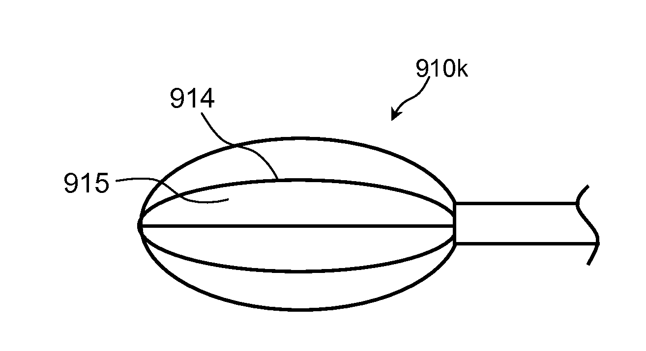
[0024]According to one aspect of the present disclosure, ureteral stents are provided that comprise an elongated stent body, at least one deployable retention structure (e.g., a kidney coil, a bladder coil, or both), and at least one sleeve of drug-releasing material (also referred to herein as a “drug-releasing sleeve”).

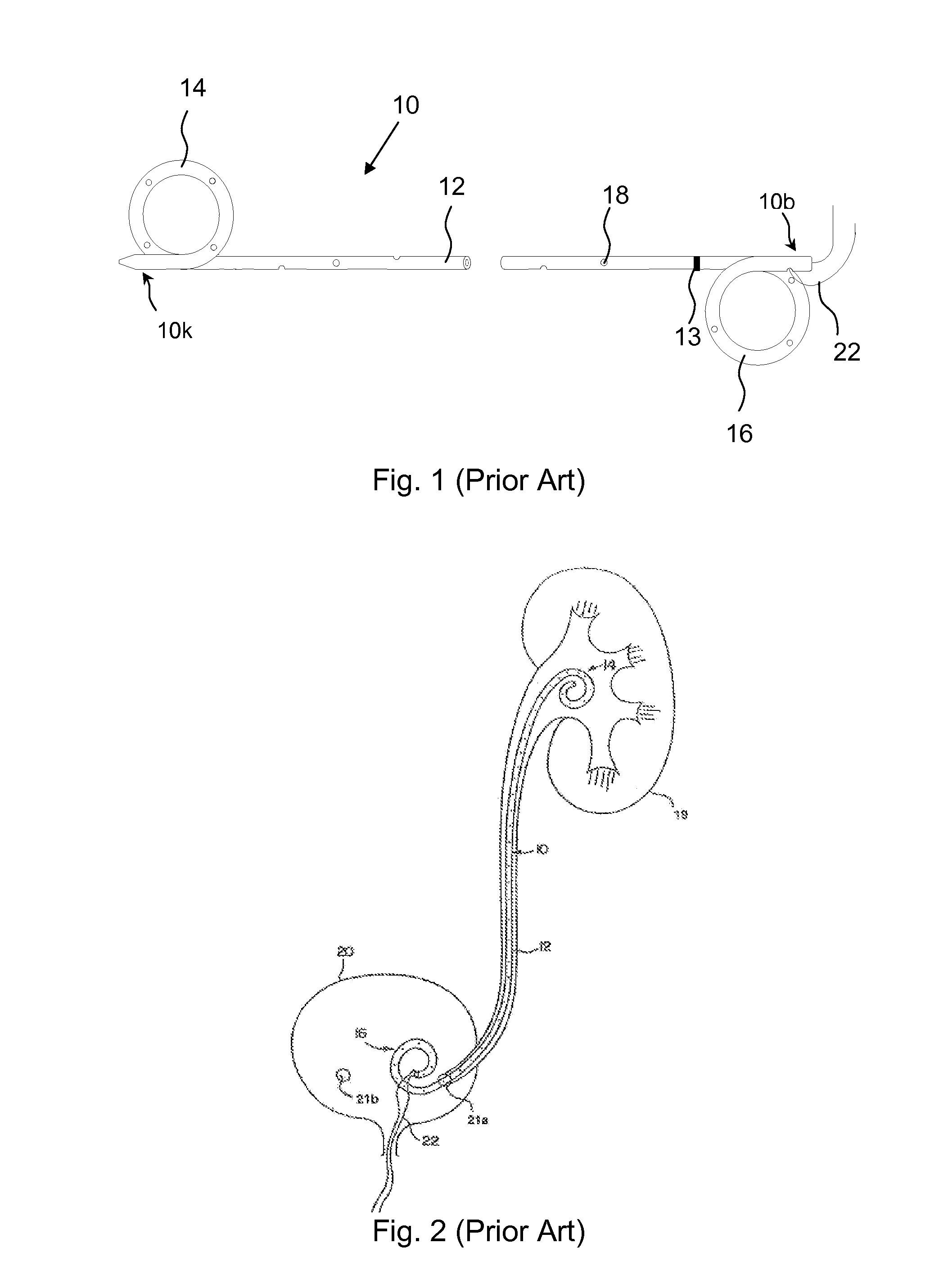
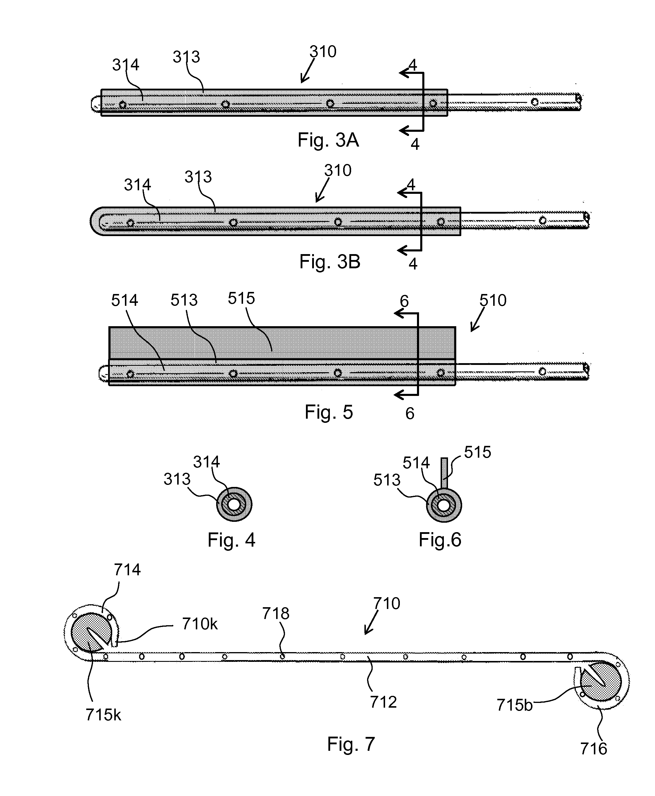
[0025]For example, FIGS. 3A and 3B are schematic illustrations of a kidney coil portion 314 of ureteral stent 310 in linear form, in accordance with two embodiments of the present disclosure. A kidney coil portion 314 may be placed in substantially linear form, for example, by placing the stent 310 over a guidewire (not shown), with the kidney coil portion 314 returning to its natur...


PUM

PropertyMeasurementUnit
Thicknessaaaaaaaaaa
Thicknessaaaaaaaaaa
Thicknessaaaaaaaaaa

Abstract

According to one aspect of the present disclosure, ureteral stents are provided that comprise an elongated stent body, at least one deployable retention structure, and at least one sleeve and/or sheet of drug-releasing material. In various embodiments, at least one sleeve and/or sheet of drug-releasing material is deployed concurrently with the deployment of at least one deployable retention structure. The ureteral stents of the present disclosure are adapted to release the urologically beneficial drug into a subject.

Description

STATEMENT OF RELATED APPLICATION[0001]This application claims the benefit of U.S. Ser. No. 61 / 758,464, filed Jan. 30, 2013 and entitled “URETERAL STENT WITH DRUG-RELEASING STRUCTURE,” which is hereby incorporated by reference in its entirety.FIELD OF THE INVENTION[0002]The present invention relates generally to ureteral stents, and more particularly to ureteral stents which release drugs within the body of a patient.BACKGROUND OF THE INVENTION[0003]Ureteral stents are widely used to facilitate drainage in the upper urinary tract (e.g., from the kidney to the bladder), for example, following ureteroscopy, endourerotomies, and endopyelotomy for ureteral strictures, as well as in other instances where ureteral obstruction may occur, for example, following lithotripsy.[0004]A schematic diagram of a stent 10 in accordance with the prior art is schematically illustrated in FIG. 1. The stent 10 comprises an elongated stent body in the form of a tubular polymeric extrusion including a renal...

Claims


Application Information

Patent Timeline
IPC IPC(8): A61F2/04
CPCA61F2/04A61M27/008A61K31/00A61K9/0036A61L31/148A61L31/16A61F2210/0004A61F2220/0008A61F2250/0067A61F2002/048
Inventor BARRON, HEIDI J.LI, JIANMIN
Owner BOSTON SCI SCIMED INC
Why Eureka
Try Eureka