Object detector

Active Publication Date: 2014-07-31
FUJITSU GENERAL LTD
View PDF5 Cites 8 Cited by
  • Summary
  • Abstract
  • Description
  • Claims
  • Application Information

AI Technical Summary

Benefits of technology

[0009]Changing the prescribed steering angle range corresponding to a condition of the steering angle in accordance with the acquired velocity allows for relaxing a condition for enabling the detection function of the detector. Therefo

Problems solved by technology

The frame correlation method described above, however, has the characteristics that it is more difficult to detect an object accurately when the vehicle where the object detection system is installed is turning

Method used


Image

  • Object detector
  • Object detector
  • Object detector

Examples


Example

1. First Embodiment

[0038]

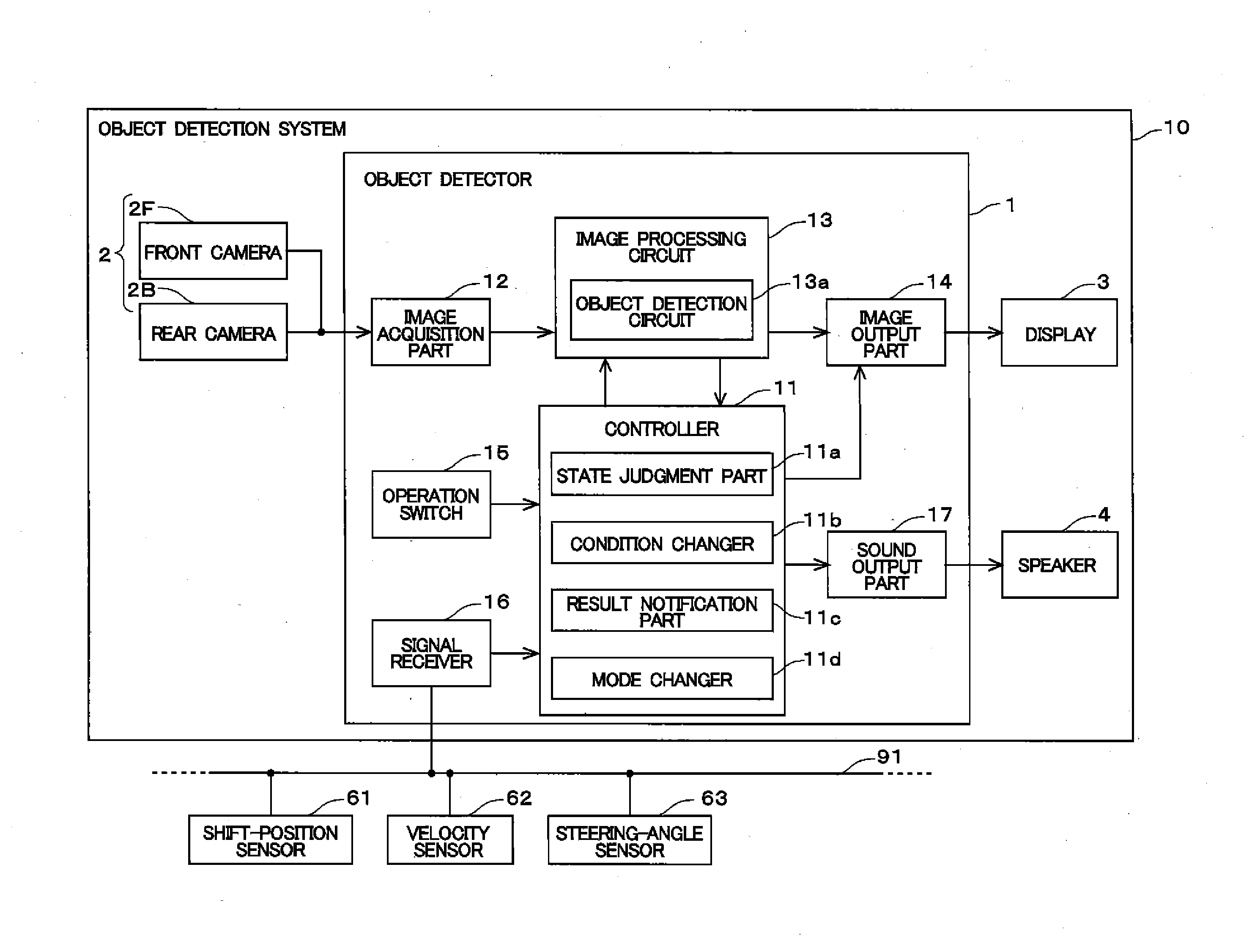
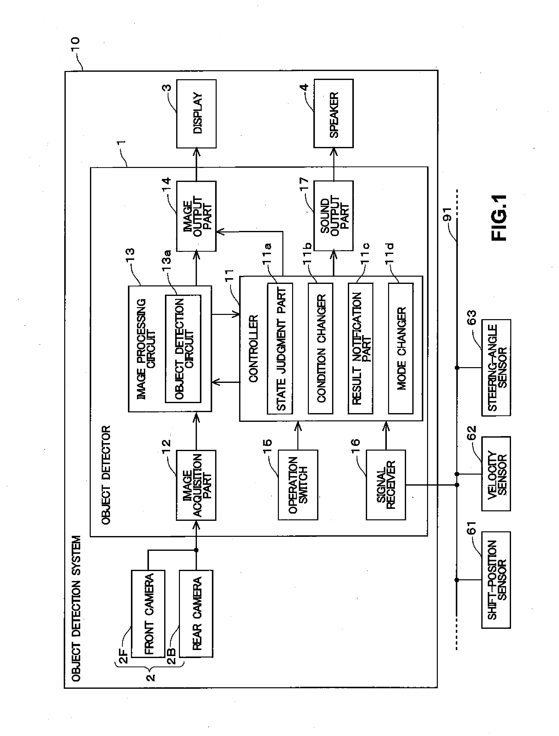
[0039]FIG. 1 shows a schematic configuration of an object detection system 10 of the embodiment. The object detection system 10 for installation in a vehicle such as a car has a function for detecting an object moving in the periphery of the vehicle, and then informing a user of the result of a detected object, if any. Hereafter, the vehicle equipped with the object detection system 10 is referred to as “own vehicle.”

[0040]The object detection system 10 includes a display 3 that displays a shot image and a speaker 4 that generates sound. The display 3 is located at a position that a user (primarily a driver) can see in a vehicle cabin of the own vehicle to inform the user of various types of information. The display 3 may have a navigation function for providing route guidance to a destination, and / or a touch panel function for receiving a user operation. The speaker 4 is located in the vehicle cabin of the own vehicle to inform the user of information with ...

Example

2. Second Embodiment

[0117]Next, the second embodiment is described. The configuration and the processing on an object detection system 10 of the second embodiment are substantially the same as the ones of the first embodiment. Thus, the points different from the first embodiment are primarily described. On the first embodiment, the state judgment part 11a judges whether enabling the detection function of the object detection circuit 13a is acceptable or not, based on the velocity and the steering angle of the own vehicle 9. In the second embodiment, a state judgment part 11a judges whether enabling the detection function of an object detection circuit 13a is acceptable or not, in further consideration of the operation state of the anti-lock braking system of an own vehicle 9.

[0118]FIG. 14 shows a configuration of an object detection system 10 of the second embodiment. As shown in the figure, a signal receiver 16 of the second embodiment can receive a signal via an in-vehicle network...

Example

3. Third Embodiment

[0124]Next, the third embodiment is described. The configuration and the processing on an object detection system 10 of the third embodiment are substantially the same as the ones of the first embodiment. Thus, the points different from the first embodiment are primarily described. On the first embodiment, the state judgment part 11a judges whether enabling the detection function of the object detection circuit 13a is acceptable or not based on the velocity and the steering angle of the own vehicle 9. On the third embodiment, a state judgment part 11a judges whether enabling the detection function of an object detection circuit 13a is acceptable or not, in further consideration of the open-close state of a rear door 92 in a back mode M3.

[0125]FIG. 15 shows the configuration of the object detection system 10 of the third embodiment. As shown in the figure, a signal receiver 16 of the third embodiment can receive a signal via an in-vehicle network 91 from a courtesy...


PUM


Abstract

An object detection circuit detects an object moving in a periphery of a vehicle by a frame correlation method that uses a plurality of shot images captured at successive times. A state judgment part disables a detection function of the object detection circuit when a steering angle of an own vehicle is not in a prescribed steering angle range. Then, a condition changer changes the prescribed steering angle range corresponding to a condition of the steering angle in accordance with a velocity of the own vehicle. Therefore, the condition changer can relax the condition for enabling the detection function in accordance with the velocity of the own vehicle within a range where detection accuracy is ensured.

Description

BACKGROUND OF THE INVENTION[0001]1. Field of the Invention[0002]The invention relates to a technology for detecting an object moving in the periphery of a vehicle.[0003]2. Description of the Background Art[0004]Conventionally, object detection systems each of which detects an object by use of the shot image of the periphery of a vehicle captured by a camera have been proposed. In an example, an object detection system detects an object based on the shot image captured by a front camera, and displays on a display an indication or the like that shows the detected result. By use of such an object detection system, a user (mainly a driver) can easily perceive the object such as another vehicle approaching from the location that the user cannot see at an intersection with a poor view, a parking area or the like.[0005]A frame correlation method that uses a plurality of shot images captured at successive times is known as a method for detecting an object on such an object detection system....

Claims


Application Information

Patent Timeline
IPC IPC(8): B60R1/00
CPCB60R1/002B60R1/00B60R2300/70B60R2300/00B60R2300/605B60R2300/802
Inventor YAMAMOTO, TETSUO
Owner FUJITSU GENERAL LTD
Why Eureka
Try Eureka