Air coupled ultrasonic contactless method for non-destructive determination of defects in laminated structures
- Summary
- Abstract
- Description
- Claims
- Application Information
AI Technical Summary
Benefits of technology
Problems solved by technology
Method used
Image
Examples
example 1
Negative Detection of Timber Defects
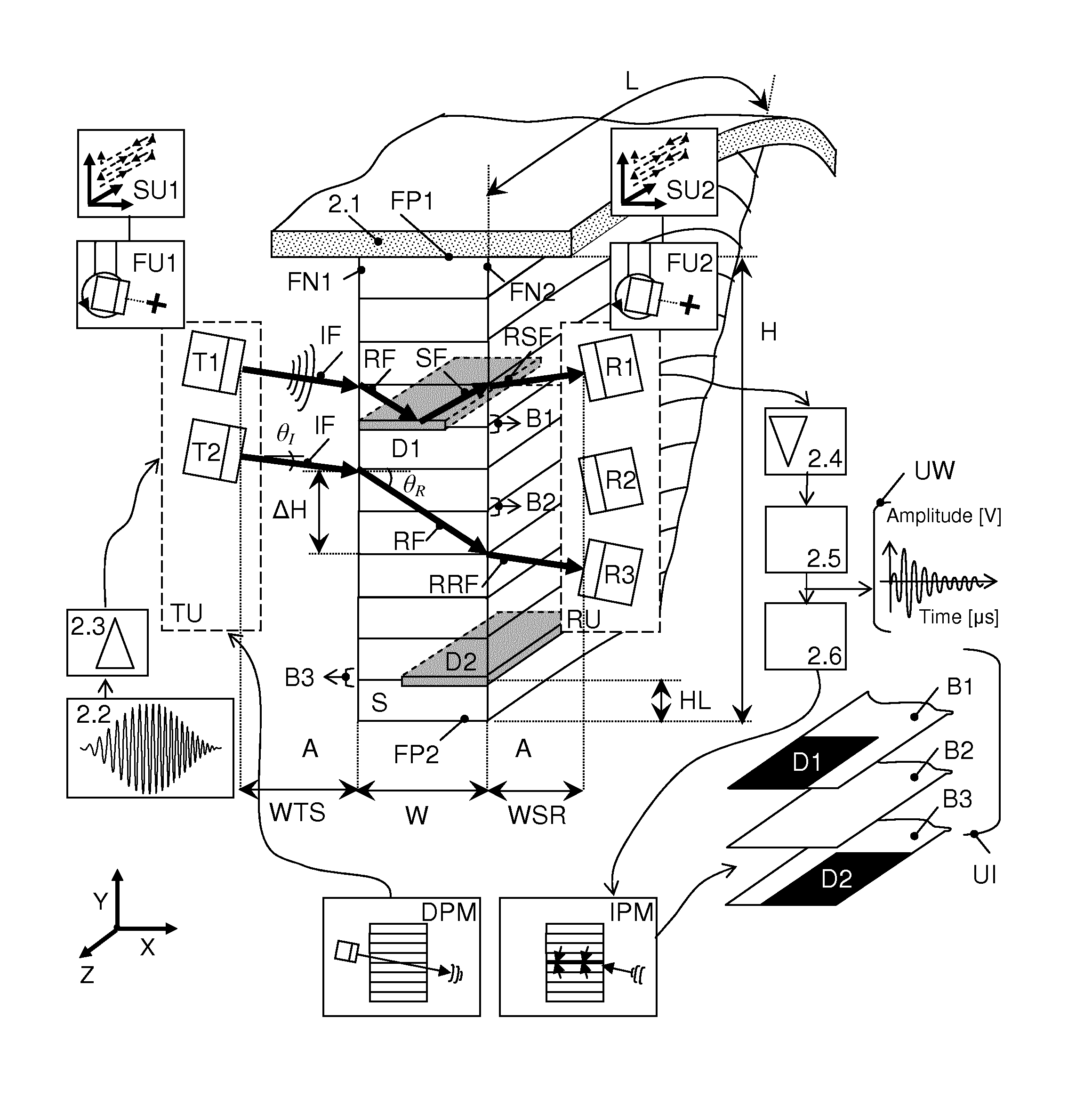
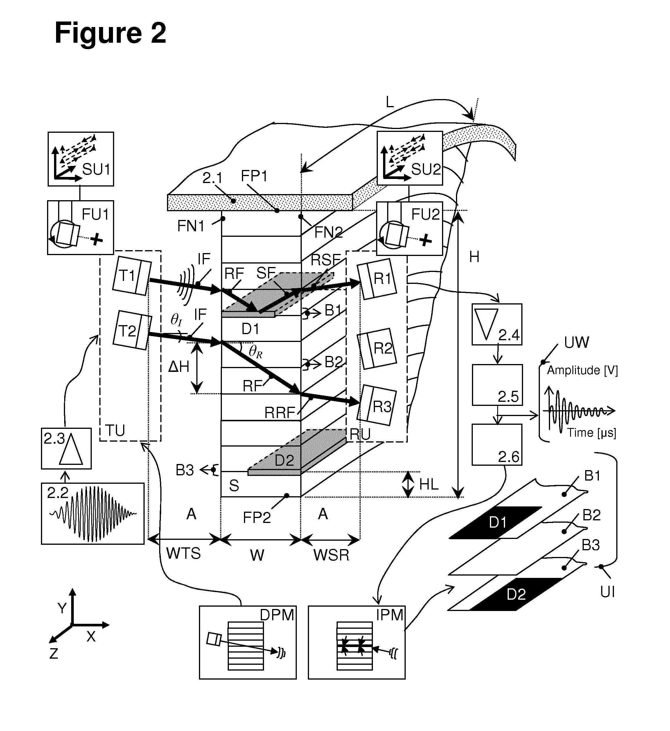
[0129]FIGS. 9a1 and 9b1 are showing two specific experimental implementations of an installation according to the negative detection ultrasound inspection setup described in FIG. 3a together with recorded ultrasound signals (FIGS. 9a3, 9a4, 9b3, 9b4) for a typical glued laminated timber beam and imaging results (FIGS. 9a3, 9b2) for individual bonding planes.
Materials and Methods
[0130]The inspected sample S is a commercial glued laminated timber beam made from coniferous wood (Picea abies Karst.), which dimensions are L=500 mm, W=160 mm, H=245 mm. The mean height of the lamellas is HL=40 mm. A lamination defect D, specifically a non-glued region, was introduced in the bonding plane B2 for half of the beam length L / 2 (160×250 mm2).
[0131]A single transmitter T and a single receiver transducer R were implemented with off-the-shelf gas matrix piezoelectric composites (The Ultran Group, Inc.) with a 30 dB bandwidth between 70 and 180 kHz. The transducer...
example 2
Positive Detection of Timber Defects
[0146]FIG. 10a1 shows an experimental implementation of the invention according to the positive detection ultrasound inspection setup described in FIG. 3b together with recorded ultrasound signals (FIG. 10a3, FIG. 10a4) for a typical glued laminated timber beam and imaging results for individual bonding planes (FIG. 10a2).
Materials and Methods
[0147]The inspected sample S is a commercial glued laminated timber beam made from coniferous wood (Picea abies Karst), which dimensions are L=280, W=200, H=280. The mean height of the lamellas is HL=40 mm. A lamination defect D, specifically a saw cut, was introduced in the fourth lamination for half of the beam length (200×250 mm2).
[0148]The positive detection configuration of FIG. 10a1 was implemented with a similar experimental setup to FIG. 9a1. The transmitter T and receiver R transducers, the excitation signal, the settings of the acquisition equipment, the data evaluation and amplitude imaging procedu...
example 3
Characterization of Total Re-Radiated Sound Field Scattered at Timber Defects
[0152]FIGS. 11a1 and 11b1 shows specific installations according to the sound field scanning setup described in FIG. 6c together with ultrasound images (FIGS. 11a2, 11b2) of the typical sound field distribution scattered at a timber defect area D and re-radiated into air, and ultrasound waveforms (FIGS. 11a3, 11a4, 11b3, 11b4) recorded at specific scan positions.
Materials and Methods
[0153]The inspected sample S is a commercial glued laminated timber beam made from coniferous wood (Picea abies Karst.), which dimensions are L=320, W=135, H=300. The mean height of the lamellas is HL=35 mm. A lamination defect D, specifically an air gap, was introduced in the fourth lamination (135×320 mm2).
[0154]The sound field scanning configuration of FIG. 6b was implemented for a positive detection setup similar to FIG. 10. Two ultrasound transducers, namely transmitter T and receiver R were used. The transmitter T was a pl...
PUM
 Abstract
Description
Claims
Application Information
 - R&D
- Intellectual Property
- Life Sciences
- Materials
- Tech Scout
- Unparalleled Data Quality
- Higher Quality Content
- 60% Fewer Hallucinations
Browse by: Latest US Patents, China's latest patents, Technical Efficacy Thesaurus, Application Domain, Technology Topic, Popular Technical Reports.
© 2025 PatSnap. All rights reserved.Legal|Privacy policy|Modern Slavery Act Transparency Statement|Sitemap|About US| Contact US: help@patsnap.com


