Non-oriented Electrical Steel Strip Having Excellent Magnetic Properties and Production Method Thereof

a technology of non-oriented electrical steel and production method, which is applied in the direction of magnetism of magnetic bodies, magnetic materials, inorganic material magnetism, etc., can solve the problems of affecting grain growth, and increasing the production cost of steel

Inactive Publication Date: 2014-08-07
HEO NAM HOE +7
View PDF2 Cites 6 Cited by
  • Summary
  • Abstract
  • Description
  • Claims
  • Application Information

AI Technical Summary

Problems solved by technology

In the case of the former, the production cost of the steel is increased due to additional processes, and in the case of the latter, the additional elements increase the production cost of the steel.
For this reason, as the slab reheating temperature increases, the amount of [Al], [N], [Mn] and [S], which result from dissolution, increases and thus interferes with grain growth in the final

Method used


Image

  • Non-oriented Electrical Steel Strip Having Excellent Magnetic Properties and Production Method Thereof
  • Non-oriented Electrical Steel Strip Having Excellent Magnetic Properties and Production Method Thereof
  • Non-oriented Electrical Steel Strip Having Excellent Magnetic Properties and Production Method Thereof

Examples


example 1

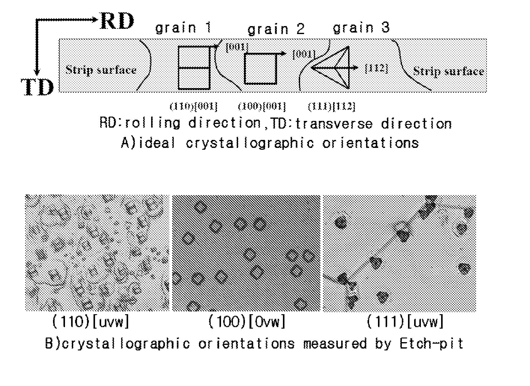
[0113]A hot-rolled strip having the composition shown in A of Table 1 was annealed at 1050° C., after which it was pickled and cold-rolled, thereby producing a cold-rolled steel strip having a thickness of 0.20 mm. The cold-rolled steel strip was finally annealed at 1,300° C. for 600 seconds without being subjected to first-stage annealing. FIG. 5 shows the results of this example, and as can be seen therein, the crystallographic orientation was not a complete (100%) (100) [0vw], but was 47% (100) [0vw] and 52% (111) [uvw].

example 2

[0114]A hot-rolled strip having the composition shown in A of Table 1 was annealed at 1050° C., after which it was pickled and cold-rolled, thereby producing a cold-rolled steel strip having a thickness of 0.20 mm. In a final annealing process, the cold-rolled steel strip was subjected to first-stage annealing at 850° C. for 540 seconds, and then subjected to second-stage annealing at 1300° C. for 15 seconds. FIG. 6 shows the results of this example, and as can be seen therein, a non-oriented electrical steel strip structure consisting of about 89% (100) [0vw] and 11% (111) [uvw] was obtained.

example 3

[0115]A hot-rolled strip having the composition shown in A of Table 1 was annealed at 1050° C., after which it was pickled and cold-rolled, thereby producing a cold-rolled steel strip having a thickness of 0.20 mm. In a final annealing process, the cold-rolled steel strip was subjected to first-stage annealing at 850° C. for 540 seconds, and then subjected to second-stage annealing at 1300° C. for 60 seconds. FIG. 7 shows the results of this example, and as can be seen therein, a complete (100%) (100) [0vw] non-oriented electrical steel strip structure was obtained. FIG. 8 shows the Etch-pit structure of the produced steel strip. As can be seen in FIG. 8, the steel strip shows an Etch-pit form in which the main orientation of the complete (100%) (100) [0vw] orientation is (100) [012].


PUM

PropertyMeasurementUnit
Temperatureaaaaaaaaaa

Abstract

The present invention relates to a non-oriented electrical steel strip, which is used as a core for electrical devices such as motors and transformers, and a production method thereof. In accordance with one embodiment of the invention, there is provided a method for producing a (100) [0vw] non-oriented electrical steel strip having excellent magnetic properties, in which a slab having a composition comprising 0.0001-0.035 wt % of S and the balance of Fe and inevitable impurities, thereby showing a ferrite structure throughout the entire temperature range, is hot-rolled, pickled and cold-rolled, and the cold-rolled steel strip is annealed so that the selective growth of (100) grains on the surface of the cold-rolled steel strip occurs and the surface of the annealed steel strip is composed of the (100) [0vw] orientation.

Description

TECHNICAL FIELD[0001]The present invention relates to a non-oriented electrical steel strip, which is used as a core for electrical devices such as motors and transformers, and a production method thereof, and more particularly to a (100) [0vw] non-oriented electrical steel strip having excellent magnetic properties and a production method thereof.BACKGROUND ART[0002]In recent years, the use of electrical devices in high-frequency regions has increased for the purpose of high efficiency and miniaturization. Particularly, in the case of power generators for electric vehicles, an improvement of magnetic properties in a high-frequency region of 400-1,000 Hz. has been strongly required.[0003]Non-oriented electrical steel strips are important parts required for converting electrical energy into mechanical energy in electrical devices, and the magnetic properties thereof need to be improved. In other words, it is necessary to lower the core loss and increase the magnetic flux density.[000...

Claims


Application Information

Patent Timeline
IPC IPC(8): H01F1/16H01F1/147C21D8/02
CPCH01F1/16H01F1/14791C21D8/0263C22C38/02C22C38/001C22C38/002C22C38/004C22C38/04C22C38/06C21D8/1222C21D8/1233C21D8/1261
Inventor HEO, NAM-HOE
Owner HEO NAM HOE
Why Eureka
Try Eureka