Carbon nanotube fiber and method for producing the same

Inactive Publication Date: 2014-08-07
HONDA MOTOR CO LTD
View PDF6 Cites 32 Cited by
  • Summary
  • Abstract
  • Description
  • Claims
  • Application Information

AI Technical Summary

Benefits of technology

[0008]As a result of extensive and intensive studies, the present inventors have found that, in the conventional twisted carbon nanotube

Problems solved by technology

However, there is an inconvenience that the conventional twisted

Method used


Image

  • Carbon nanotube fiber and method for producing the same
  • Carbon nanotube fiber and method for producing the same
  • Carbon nanotube fiber and method for producing the same

Examples


example 1

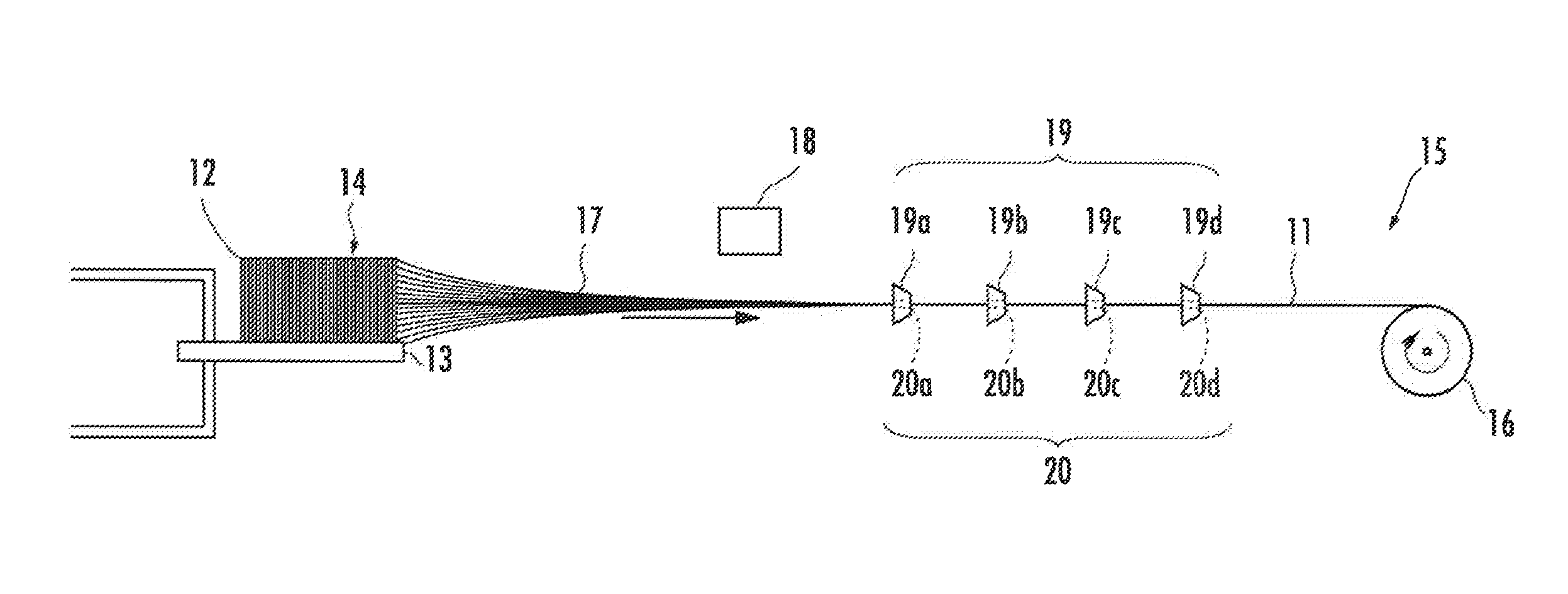
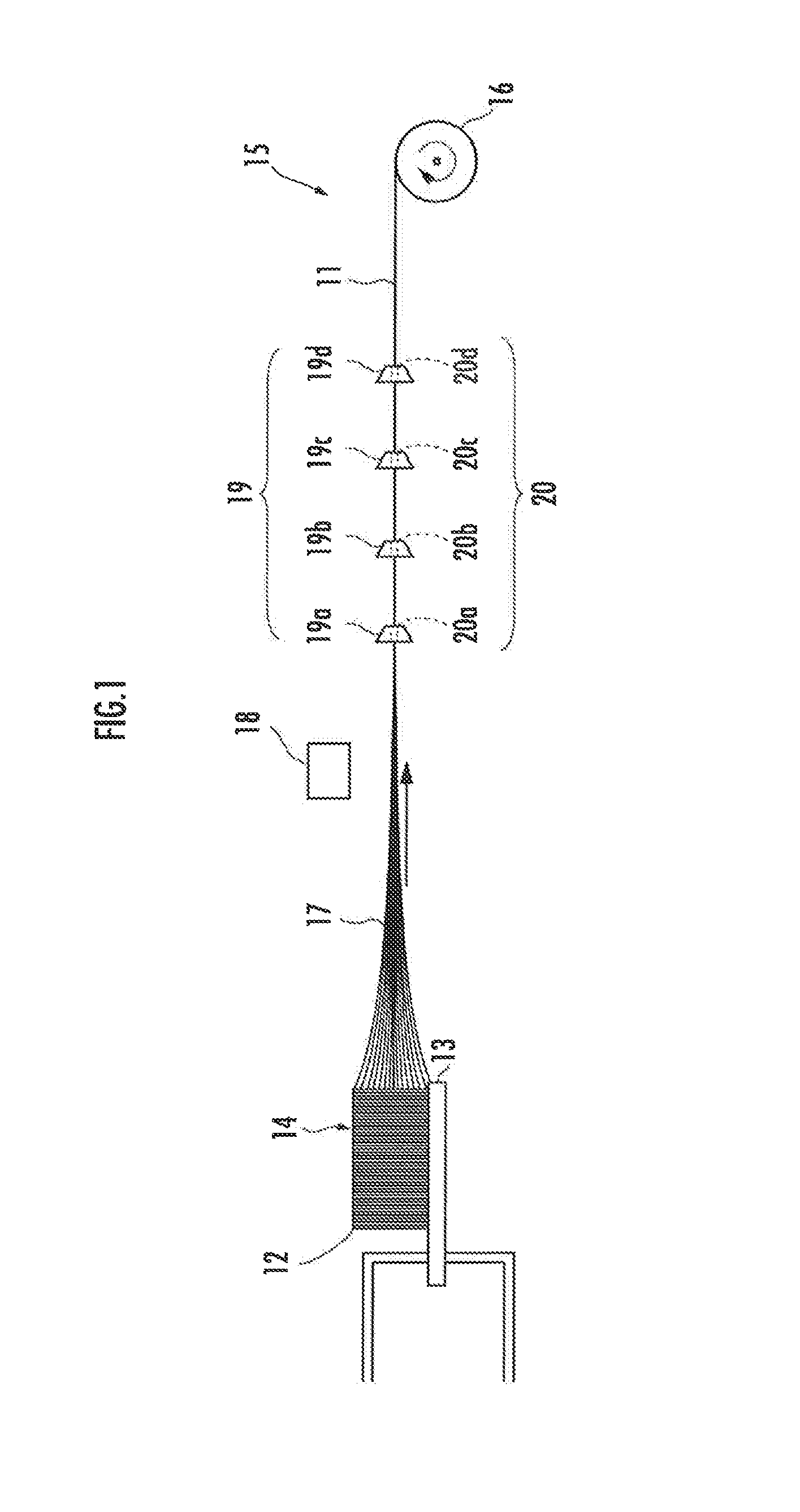
[0087]In this Example, a plurality of carbon nanotubes 12 were first grown by a CVD method on a silicon substrate 13 (5 cm in length, 5 cm in width, and 500 μm in thickness) on which an Al film (5 μm in thickness) and a Fe film (2 μm in thickness) had been deposited to form a carbon nanotube forest 14. In the resulting carbon nanotube forest 14, the carbon nanotubes 12 had an average diameter of 10.6 nm, an average length of 394 μm, and a density of 84 mg / cm3.

[0088]Next, in a spinning apparatus 15 shown in FIG. 1, a plurality of carbon nanotubes 12 were paralleled in a state where they are not twisted from the carbon nanotube forest 14 by a drawing unit 16 to thereby form a carbon nanotube assembly 17 in which the plurality of the carbon nanotubes 12 are assembled.

[0089]Next, after impurities in the resulting carbon nanotube assembly 17 were removed by a blower as an impurity removing unit 18, the carbon nanotube assembly 17 was successively inserted into the pores 20a, 20b, 20c, an...

example 2

[0095]In this Example, a carbon nanotube assembly 17 was first formed in exactly the same manner as in Example 1.

[0096]Next, a carbon nanotube fiber 11 was formed in exactly the same manner as in Example 1 except that the resulting carbon nanotube assembly 17 was inserted only into the pore 20a of the die 19a.

[0097]Next, the cross section of the resulting carbon nanotube fiber 11 was observed by SEM to thereby determine the cross-sectional filling rate, and it was found to be 9.0%.

[0098]FIG. 9A shows an enlarged front picture of the carbon nanotube fiber 11, and FIG. 9B and FIG. 9C each show an enlarged cross-sectional picture of the carbon nanotube fiber 11. FIG. 5C and FIG. 9C reveal that the carbon nanotube fiber 11 of Example 1 is in a state where a plurality of carbon nanotubes 12 are gathered with higher density and has a higher cross-sectional filling rate as compared with the carbon nanotube fiber 11 of this Example.

[0099]Next, the resulting carbon nanotube fiber 11 was mea...

example 3

[0100]In this Example, a carbon nanotube assembly 17 was first formed in exactly the same manner as in Example 1.

[0101]Next, a carbon nanotube fiber 11 was formed in exactly the same manner as in Example 1 except that the resulting carbon nanotube assembly 17 was inserted into the pore 20a of the die 19a and the pore 20b of the die 19b.

[0102]Next, the resulting carbon nanotube fiber 11 was measured for a cross-sectional filling rate, electrical conductivity, tensile strength, and rigidity in exactly the same manner as in Example 1, and the cross-sectional filling rate, electrical conductivity, tensile strength, and rigidity were found to be 18.2%, 170 S / cm, 0.23 GPa, and 10.8 GPa, respectively. The results are shown in Table 1 and FIGS. 6, 7, and 8.


PUM

PropertyMeasurementUnit
Lengthaaaaaaaaaa
Fractionaaaaaaaaaa
Angleaaaaaaaaaa

Abstract

There are provided carbon nanotube fibers having excellent mechanical property and a method for producing the same. In a long carbon nanotube fiber 11 in which a plurality of carbon nanotubes 12 are assembled, the carbon nanotubes 12 comprise a diameter ranging from 0.4 to 100 nm and are oriented in an angle ranging from 0 to 5° with respect to axial direction of the carbon nanotube fiber 11.

Description

BACKGROUND OF THE INVENTION[0001]1. Field of the Invention[0002]The present invention relates to carbon nanotube fibers and a method for producing the same.[0003]2. Description of the Related Art[0004]The use of carbon nanotube fibers in which a plurality of carbon nanotubes are assembled in a long shape for electronic devices, conductive wires, batteries, fiber-reinforced plastics, and the like has been studied. The carbon nanotube fibers are required to have excellent mechanical property, such as a tensile strength and a rigidity, for use in the applications as described above.[0005]A twisted carbon nanotube fiber 32 composed of a plurality of carbon nanotubes 31, for example, as shown in FIG. 2 has conventionally been known as a carbon nanotube fiber. The twisted carbon nanotube fiber 32 is formed by twisting a plurality of carbon nanotubes 31 in a spinning apparatus 33, wherein the plurality of the carbon nanotubes 31 are paralleled by a drawing unit 37 from a carbon nanotube fo...

Claims


Application Information

Patent Timeline
IPC IPC(8): C01B31/02
CPCC01B31/022C01B31/0253C01B31/0226C01B2202/08C01B2202/34C01B2202/36B82Y30/00B82Y40/00D01F9/12D02G3/36D10B2101/122C01B32/158C01B32/16C01B32/168C01B32/17
Inventor NIKAWA, HIDEFUMIOHTA, MASAHIROTOKUNE, TOSHIO
Owner HONDA MOTOR CO LTD
Why Eureka
Try Eureka