Arrangement for deploying co-existing gpon and xgpon optical communication systems

a technology of optical communication system and co-existing gpon, which is applied in the field of systems for deploying a passive optical network, can solve the problems of negating some of the advantages of purely passive systems, limited maximum transmission distance, and split ratio 1:n, and achieves the effect of increasing the reach and split ratio parameters of the overall system communication, and simplifying the components of each onu

Active Publication Date: 2014-08-07
OFS FITEL LLC
View PDF25 Cites 36 Cited by
  • Summary
  • Abstract
  • Description
  • Claims
  • Application Information

AI Technical Summary

Benefits of technology

[0017]In accordance with the present invention, a passive, co-existing XGPON and GPON compatible system is created by using a pair of counter-propagating laser pump sources at an OLT to provide Raman amplification for the upstream GPON and XGPON signals along an extended portion of the feeder fiber. A passive remote node formed in accordance with the present invention utilizes a cyclic WDM and separate power splitters for the GPON and XGPON signals. The use of separate power splitters for each data rate allows for the splitting ratios associated with each communication network to be separately optimized. The configuration of the remote node to independently process the GPON and XGPON signals allows for the architecture of the present invention to handle bot...

Problems solved by technology

However, the maximum transmission distance (referred to hereinafter at times as “reach”) between OLT 12 and the farthest away ONU 14, as well as the split ratio 1:N, are currently limited by various physical layer limitations and the PON protocol.
As a result, these designs negate some of the advantages of purely passive systems and may not always be practical or cost effective for network service providers/operators, particularly in certain environ...

Method used


Image

  • Arrangement for deploying co-existing gpon and xgpon optical communication systems
  • Arrangement for deploying co-existing gpon and xgpon optical communication systems
  • Arrangement for deploying co-existing gpon and xgpon optical communication systems

Examples


Embodiment Construction

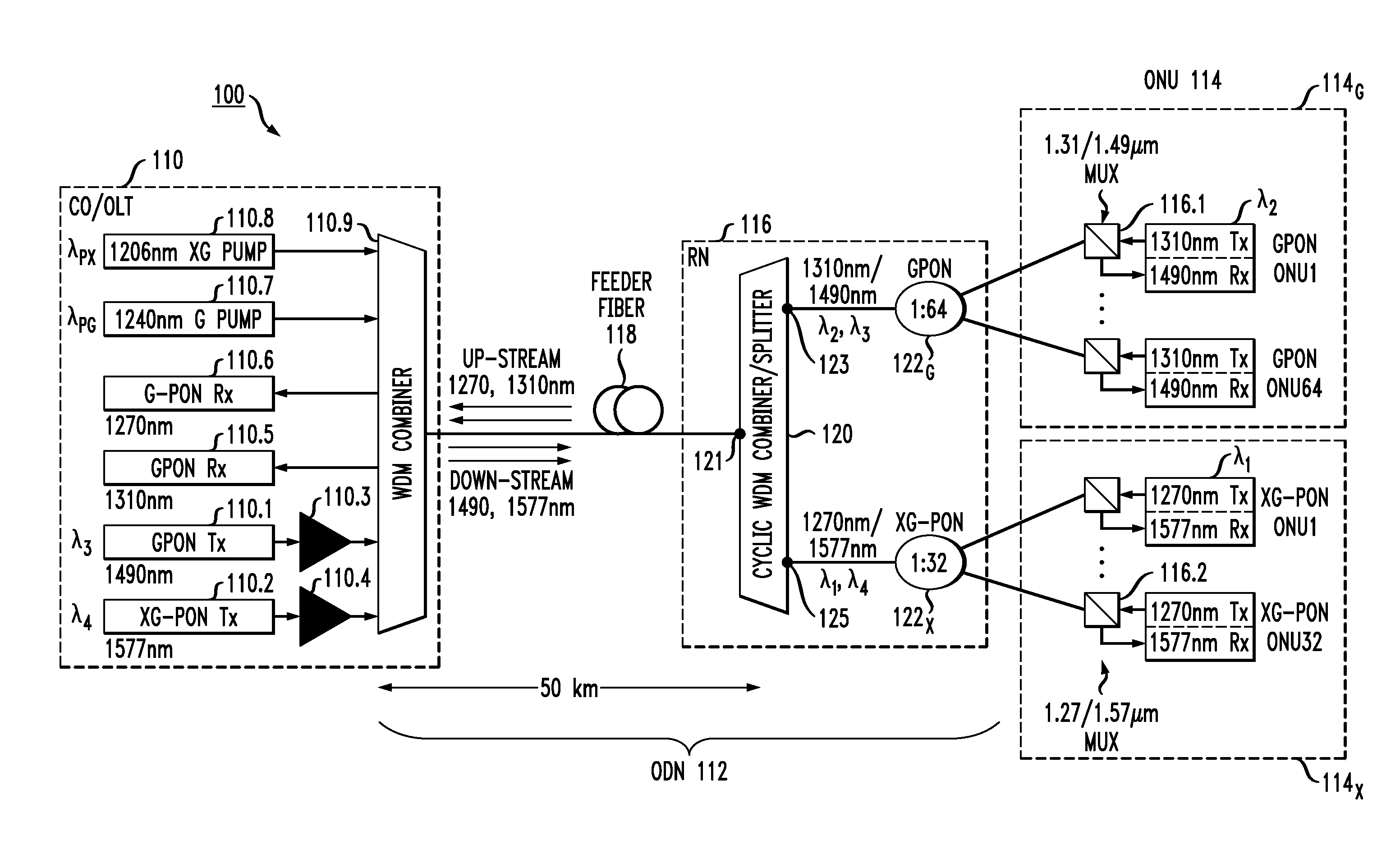
[0040]FIG. 3 illustrates an exemplary passive optical network (PON) 100 formed in accordance with the present invention. As with the various prior art arrangements described above, PON 100 includes an OLT, ODN and a number of remotely-located ONUs. In the specific arrangement of FIG. 3, PON 100 includes an OLT 110, an ODN 112 and a plurality of ONUs 114. As will be discussed in detail below, the plurality of ONUs 114 includes a first set of ONUs 114G associated with communications involving a GPON system and a second set of ONUs 114X associated with communications involving an XGPON system.

[0041]As mentioned above, inasmuch as separate ONUs are used for each system (GPON or XGPON), it is possible for the arrangement of the present invention to perform solely as a GPON system, solely as an XGPON system, or as a combination, co-existing GPON / XGPON system, and in each instance provide the desired goals of extended reach and increased split ratio while maintaining a passive network arch...


PUM


Abstract

A passive, coexisting 10 Gb/s passive optical network (XGPON) and Gb/s passive optical network (GPON) is created by using a pair of counter-propagating laser pump sources at a network-based optical line terminal, in combination with a feeder fiber, to create distributed Raman amplification for the upstream signals associated with both GPON and XGPON systems. A passive remote node is located at the opposite end of the feeder fiber, in the vicinity of a group of end-user locations, and includes a cyclic WDM and a pair of power splitters for the GPON and XGPON signals such that the GPON signals are thereafter directed through a first power splitter into optical network units (ONUs) specifically configured for GPON wavelengths and XGPON signals are directed through a second power splitter into ONUs configured for the XGPON wavelengths. The arrangement of the remote node allows for the reach and split ratios of the GPON and XGPON systems to be individually designed for optimum performance.

Description

CROSS-REFERENCE TO RELATED APPLICATIONS[0001]This application claims the benefit of U.S. Provisional Application Ser. No. 61 / 532,541, filed Sep. 8, 2011 and herein incorporated by reference.TECHNICAL FIELD[0002]The present invention relates to systems for deploying a passive optical network (PON) in a manner that allows for both a gigabit passive optical communication system (GPON) and a 10-gigabit passive optical communication system (XGPON) to co-exist within the same network architecture.BACKGROUND OF THE INVENTION[0003]To meet the ever-increasing demand for high-speed Internet access and services, many network operators are deploying, or planning to deploy, passive optical networks. A passive optical network (PON) is a point-to-multipoint, fiber-to-the-premises, broadband network architecture in which unpowered (“passive”) optical splitters are used to enable a single optical fiber to serve multiple customer premise locations (this single fiber referred to at times as a “feeder ...

Claims


Application Information

Patent Timeline
IPC IPC(8): H04Q11/00H04J14/02H04B10/25
CPCH04Q11/0067H04Q2011/0086H04J14/0227H04B10/2503H04J14/0282H04J14/0246H04J14/0247H04J14/025H04J14/0252H04B10/2589
Inventor ZHU, BENYUAN
Owner OFS FITEL LLC
Why Eureka
Try Eureka