Condition Monitoring Of An Industrial Robot

a robot and condition monitoring technology, applied in the direction of mechanical roughness/irregularity measurement, program control, instruments, etc., can solve the problems of high maintenance cost, difficult to construct an accurate friction model which can describe the effects of speed, load, temperature and wear, and high maintenance cost. , to achieve the effect of reducing impact and strong impa

Active Publication Date: 2014-08-07
ABB (SCHWEIZ) AG
View PDF4 Cites 13 Cited by
  • Summary
  • Abstract
  • Description
  • Claims
  • Application Information

AI Technical Summary

Benefits of technology

[0018]According to one embodiment of the invention, the weighting function has joint speed as an input. Joint speed is found out to have a strong impact on the torque measurement results, and this impact can be reduced by an appropriate weighting function taking the joint speed into account.
[0019]According to one embodiment of the invention, the first torque measurement is performed at a first joint temperature, and the second torque measurement is performed at a second joint temperature, the first joint temperature being identical with the second joint temperature. Joint temperature is found out to have a strong impact on the torque measurement results, and this impact can be reduced by performing the measurements in comparable temperature conditions.

Problems solved by technology

This setup delivers high availability, reducing operational costs (e.g. small downtimes) with the drawback of high maintenance costs since unnecessary maintenance actions might take place.
The extra challenge of condition based maintenance is to define methods to determine the condition of the equipment.
In practice it is, however, difficult to construct an accurate friction model which can describe the effects of speed, load, temperature and wear.

Method used


Image

  • Condition Monitoring Of An Industrial Robot
  • Condition Monitoring Of An Industrial Robot
  • Condition Monitoring Of An Industrial Robot

Examples


Embodiment Construction

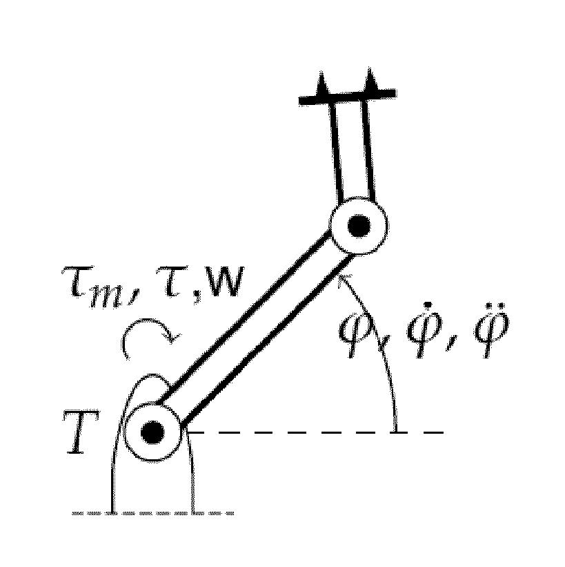
[0027]Referring to FIG. 1, an industrial robot can be described as a multi body dynamic mechanism by

τ=M(φ){umlaut over (φ)}+C(φ,{umlaut over (φ)})+Dφ+τg(φ)+τs(φ)+τf ({dot over (φ)}, τm, T, w),   (1)

where τ is torque at a robot joint, φ is an angular joint position of the robot joint, M(φ) is an inertia vector, C(φ,{dot over (φ)}) relates to speed dependent terms (e.g. Coriolis and centrifugal), D is a damping vector, τg(φ) is a gravity-induced torque, τs(φ) is a nonlinear stiffness. The function τf({dot over (φ)}, τm, T, w) contains the joint friction components and is dependent on joint speed {dot over (φ)}, the load torque τm caused by the manipulated load, the joint temperature T and the wear level w.

[0028]The deterministic input of interest is the wear level w, which is zero when the robot is new and increases with time / usage. When the wear level w exceeds a predetermined threshold value, it is considered as a fault. Since from equation (1) it is obvious that the torque T is aff...


PUM

PropertyMeasurementUnit
torqueaaaaaaaaaa
kernel density estimatorsaaaaaaaaaa
distanceaaaaaaaaaa

Abstract

A method for detecting a fault in a robot joint includes the steps of: performing a first torque measurement at the robot joint to thereby obtain a first set of torque values; calculating a first distribution characteristic reflecting a distribution of the first set of torque values; performing a second torque measurement at the robot joint to thereby obtain a second set of torque values; calculating a second distribution characteristic reflecting a distribution of the second set of torque values; and comparing the first and the second distribution characteristics to determine whether a fault is present or not. A difference in the distributions of torque measurements is a robust fault indicator that makes use of the repetitive behavior of the system.

Description

FIELD OF THE INVENTION[0001]The present invention relates to a method for detecting a fault in a robot joint.BACKGROUND OF THE INVENTION[0002]In the manufacturing industry making use of industrial robots, preventive scheduled maintenance of the robots is a common approach used to improve equipment safety, reliability, availability and maintainability. This setup delivers high availability, reducing operational costs (e.g. small downtimes) with the drawback of high maintenance costs since unnecessary maintenance actions might take place. Condition based maintenance, “maintenance when required”, can deliver a good compromise between maintenance costs and operational costs, reducing the overall costs. The extra challenge of condition based maintenance is to define methods to determine the condition of the equipment. Preferably, this should be done automatically.[0003]Conventionally in robotics, condition monitoring and fault detection methods are mainly considered in the time-domain, t...

Claims


Application Information

Patent Timeline
Patent Type & Authority Applications(United States)
IPC IPC(8): G01N19/08
CPCY10S901/46G01N19/08B25J9/1674G05B2219/37256G05B2219/37344G05B2219/40335Y02P90/80
Inventor SANDER-TAVALLAEY, SHIVASAARINEN, KARIANDERSSON, HANSBITTENCOURT, ANDRE CARVALHO
Owner ABB (SCHWEIZ) AG
Why Eureka
Try Eureka