
Spacecraft east-west radiator assembly

a radiator and east-west technology, applied in the field of heat transfer systems, can solve the problems of high thermal dissipation requirements, less effective, and additional heat rejection capability beyond, and achieve the effect of reducing the average temperature and temperature fluctuations, and facilitating access to internal equipmen

Active Publication Date: 2014-08-14
LOCKHEED MARTIN CORP
View PDF9 Cites 20 Cited by
  • Summary
  • Abstract
  • Description
  • Claims
  • Application Information

AI Technical Summary

Benefits of technology

The patent is for a heat transfer system for spacecraft that reduces the temperature and fluctuations compared to traditional systems. It also allows for separate mounting of equipment, making use of unused space in the vehicle. The system is easier to access and maintain during integration and testing, while still keeping all the necessary connections.

Problems solved by technology

As GEO spacecraft are frequently used for communication and observation, the designers must accommodate complex communications payloads with large number of components and high thermal dissipation requirements.
However, it is often the case that additional heat rejection capability is required beyond what can be provided by such north and south radiator panels.
Because east and west radiator panels receive direct sun exposure during each orbit, they are less effective than north and south radiator panels and therefore operate at higher average temperatures for an equivalent thermal load.
This generally limits the use of east and west radiator panels to equipment such as output multiplexers (OMUXs) that can operate at higher temperatures.
In addition, east and west radiator panels tend to undergo large diurnal temperature fluctuations, as the individual panels alternately face the Sun and deep space, and equipment that is thermally coupled to conventional east and west radiator panels may require significant heater power to limit the temperature fluctuations to an acceptable range.
Another drawback of conventional radiator panels is that, once the radiator panel is installed, it becomes difficult to access equipment inside the spacecraft including the equipment that is mounted on the radiator panels themselves.
This increases the cost and time required for remove-and-replace operations that may be necessary during integration and test of a conventional spacecraft.

Method used


Image

  • Spacecraft east-west radiator assembly
  • Spacecraft east-west radiator assembly
  • Spacecraft east-west radiator assembly

Examples


Embodiment Construction

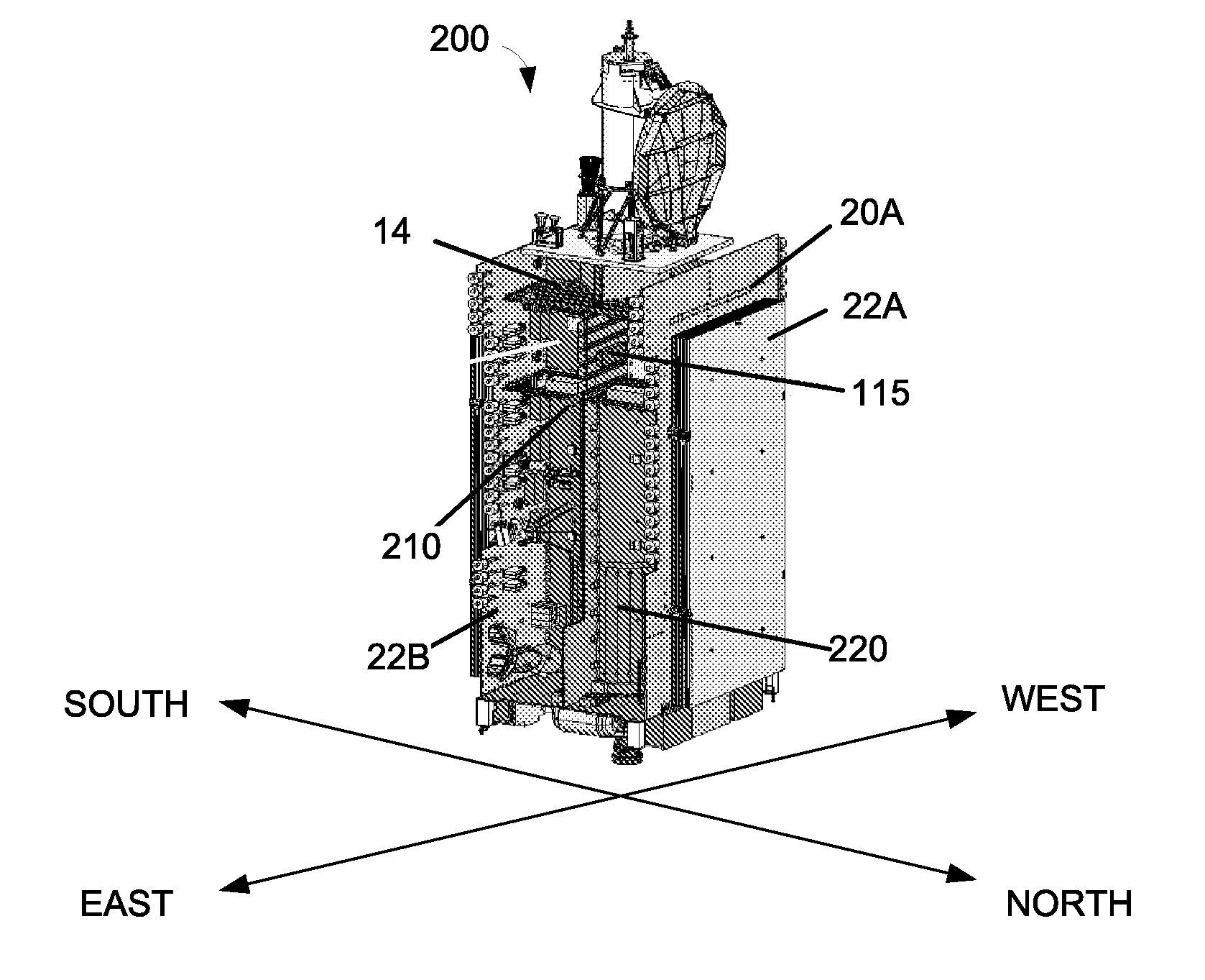
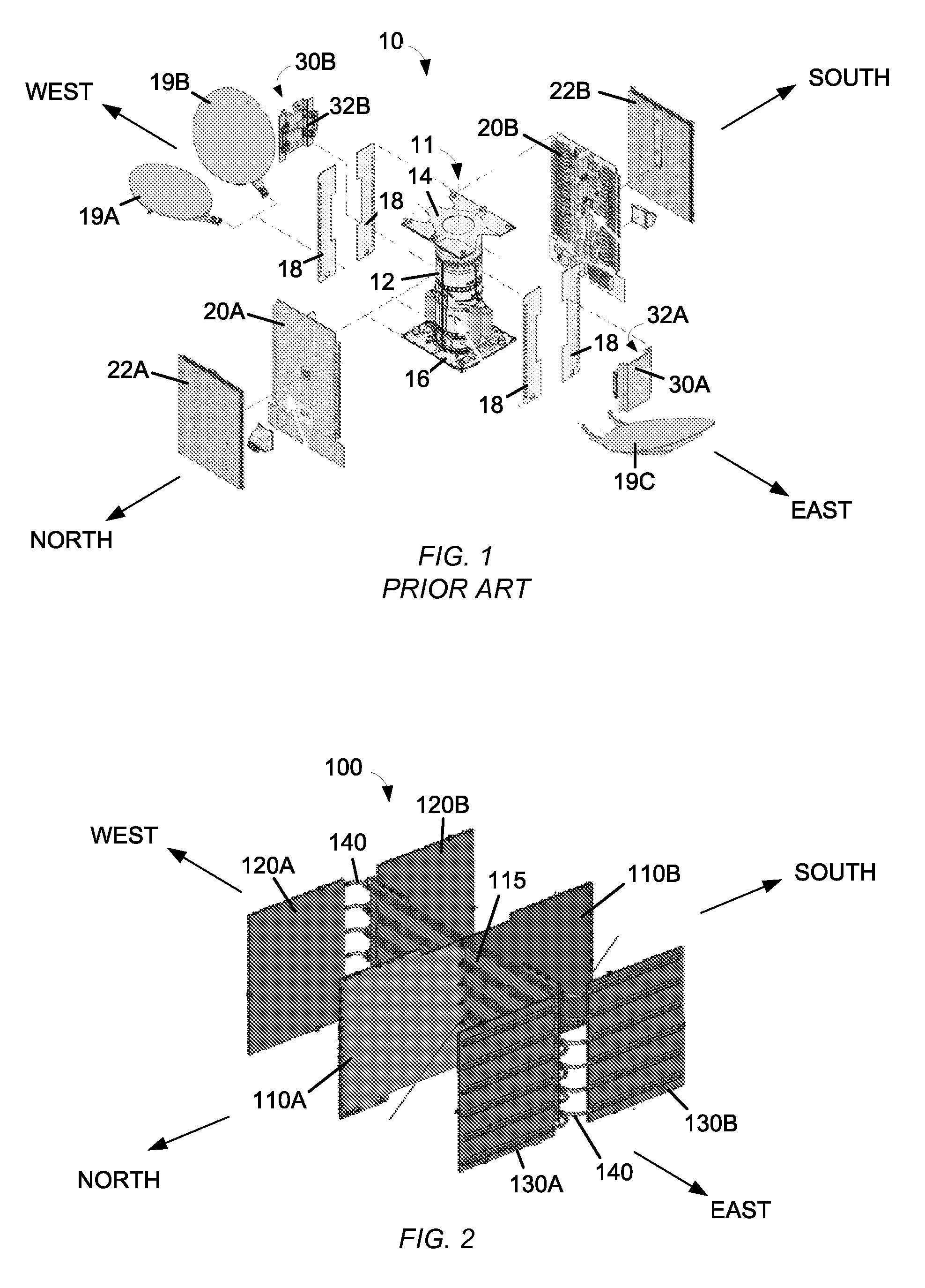
[0023]The present invention generally relates to heat-transfer systems and, in particular, to a spacecraft radiator assembly with flexible heat pipes.

[0024]The following description discloses embodiments of an east-west heat-transfer assembly that is particularly adapted for use on a GEO spacecraft. In certain embodiments, however, the same concepts and construction may be effectively used on other types of spacecraft as well as other applications where radiator panels provide a source of cooling.

[0025]The detailed description set forth below is intended as a description of various configurations of the subject technology and is not intended to represent the only configurations in which the subject technology may be practiced. The appended drawings are incorporated herein and constitute a part of the detailed description. The detailed description includes specific details for the purpose of providing a thorough understanding of the subject technology. However, it will be apparent to...


PUM


Abstract

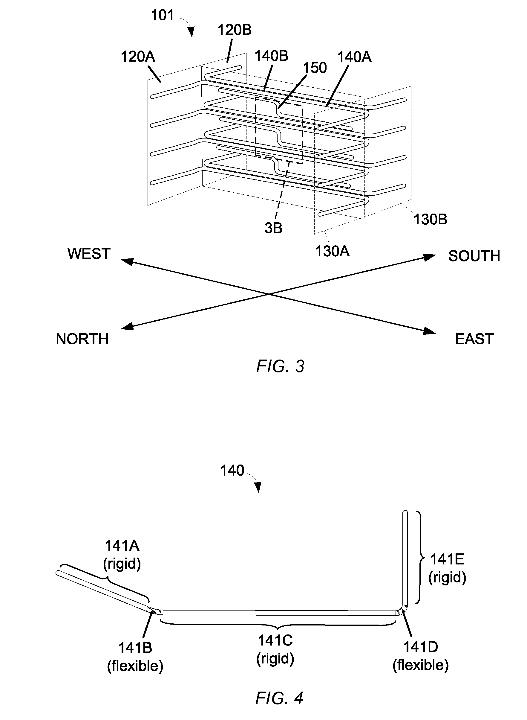
A heat transfer assembly for a spacecraft is disclosed. The assembly includes an equipment panel having an east end and a west end. East and west radiator panels are coupled to the east and west ends, respectively, of the equipment panel. The assembly also includes a plurality of flexible heat pipes each having a first rigid tube thermally coupled to the east radiator panel, a second rigid tube coupled to the equipment panel, a third rigid tube thermally coupled to the west radiator panel, a first flexible tube sealingly coupled between the first and second rigid tubes, and a second flexible tube sealingly coupled between the second and third rigid tubes. The equipment panel is configured to retain one or more equipment modules in thermal contact with the second rigid tube of at least one of the plurality of flexible heat pipes.

Description

CROSS-REFERENCE TO RELATED APPLICATIONS[0001]Not applicable.STATEMENT REGARDING FEDERALLY SPONSORED RESEARCH OR DEVELOPMENT[0002]Not applicable.BACKGROUND[0003]1. Field[0004]The present invention generally relates to heat-transfer systems and, in particular, to a spacecraft radiator assembly with flexible heat pipes.[0005]2. Description of the Related Art[0006]Spacecraft in a geosynchronous earth orbit (GEO) typically operate such that one side continuously faces toward the ground as the satellite orbits the Earth. Such a satellite will have a north-south axis that, while in orbit, is approximately parallel to the north-south rotational axis of the Earth and an east-west axis that is perpendicular to the north-south axis. As the satellite orbits the Earth, the east and west sides of the spacecraft will alternately face toward the Sun and, twelve hours later, face away from the Sun toward deep space.[0007]As GEO spacecraft are frequently used for communication and observation, the de...

Claims


Application Information

Patent Timeline
Patent Type & Authority Applications(United States)
IPC IPC(8): B64G1/50F28D15/04F28D15/02
CPCB64G1/506F28D15/04F28D15/0241F28D2021/0021B64G1/503
Inventor WONG, HAMILTONGOODZEIT, NEIL E.BUCKLEY, ROK PARKHENTOSH, DAVID J.
Owner LOCKHEED MARTIN CORP
Learn More