Large field of view grating interferometers for x-ray phase contrast imaging and ct at high energy

a phase contrast imaging and high-energy technology, applied in the field of medical imaging, can solve problems such as inability to achiev

Active Publication Date: 2014-08-14
THE JOHN HOPKINS UNIV SCHOOL OF MEDICINE
View PDF3 Cites 14 Cited by
  • Summary
  • Abstract
  • Description
  • Claims
  • Application Information

AI Technical Summary

Problems solved by technology

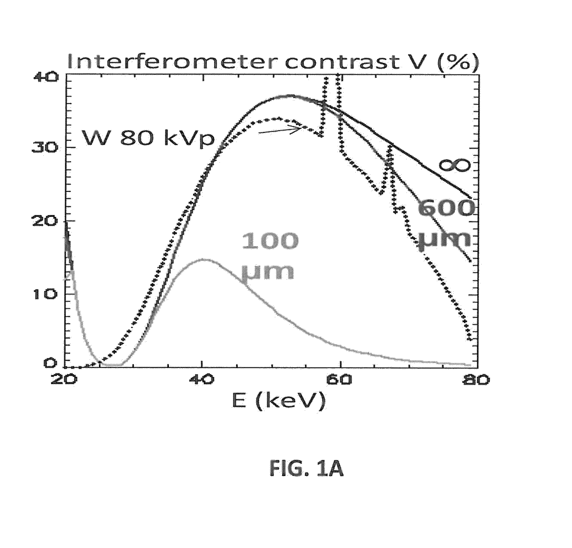
This is not possible however with the conventional normal incidence Talbot-Lau interferometer, because the thickness of few micron period absorption gratings is technologically limited to ˜100 μm.

Method used


Image

  • Large field of view grating interferometers for x-ray phase contrast imaging and ct at high energy
  • Large field of view grating interferometers for x-ray phase contrast imaging and ct at high energy
  • Large field of view grating interferometers for x-ray phase contrast imaging and ct at high energy

Examples


Embodiment Construction

[0027]Reference will now be made in detail to exemplary embodiments of the disclosure, examples of which are illustrated in the accompanying drawings. Wherever convenient, the same reference numbers will be used throughout the drawings to refer to the same or like parts.

[0028]Notwithstanding that the numerical ranges and parameters setting forth the broad scope of the disclosure are approximations, the numerical values set forth in the specific examples are reported as precisely as possible. Any numerical value, however, inherently contains certain errors necessarily resulting from the standard deviation found in their respective testing measurements. Moreover, all ranges disclosed herein are to be understood to encompass any and all sub-ranges subsumed therein. For example, a range of “less than 10” can include any and all sub-ranges between (and including) the minimum value of zero and the maximum value of 10, that is, any and all sub-ranges having a minimum value of equal to or g...


PUM

PropertyMeasurementUnit
angleaaaaaaaaaa
angleaaaaaaaaaa
angleaaaaaaaaaa

Abstract

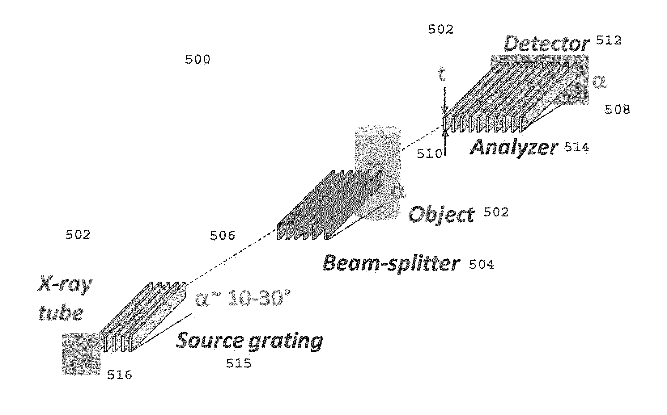
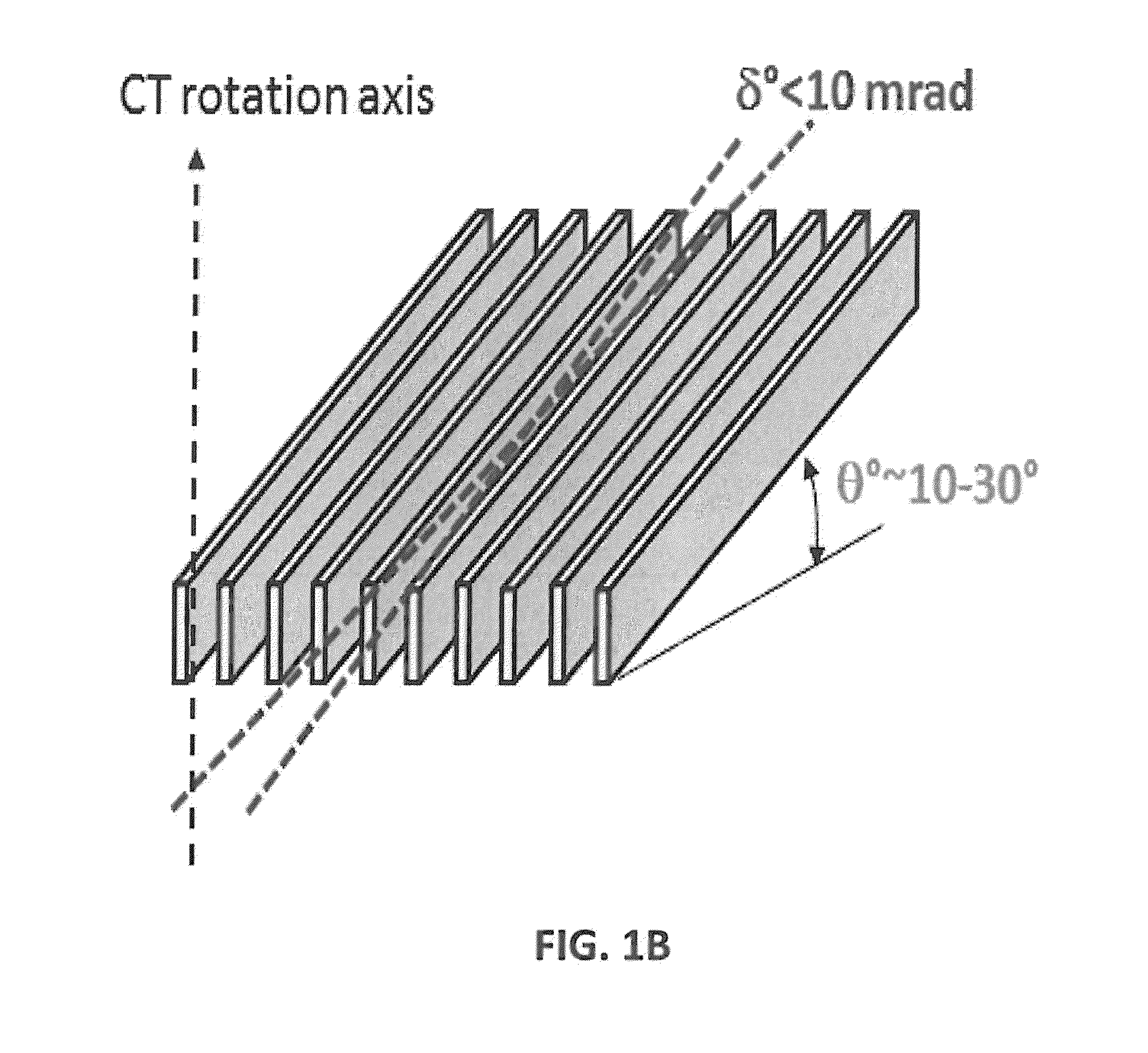
A device and method of the present disclosure provides large field-of-view Talbot-Lau phase contrast CT systems up to very high X-ray energy. The device includes microperiodic gratings tilted at glancing incidence and tiled on a single substrate to provide the large field-of-view phase contrast CT system. The present disclosure is a simple, economical, and accurate method for combining multiple GAIs into a larger FOV system, capable of performing phase-contrast tomography (PC-CT) on large objects. The device and method can be applied to medical X-ray imaging, industrial non-destructive testing, and security screening.

Description

CROSS REFERENCE TO RELATED APPLICATIONS[0001]This application is related to U.S. patent application Ser. No. 13 / 493,392, titled “Differential Phase Contrast X-ray Imaging System and Components,” filed on Jan. 31, 2013 and U.S. patent application Ser. No. 14 / 174,830, titled “System and Method for Phase-Contrast X-ray Imaging,” filed on Feb. 6, 2014 by Dan Stutman and Michael Finkenthal, and claims priority from U.S. Provisional Patent Application 61 / 763,683 titled “High Energy X-Ray Phase Contrast CT Systems Using Tiled Glancing Incidence Gratings,” filed on Feb. 12, 2013, hereby incorporated by reference in their entirety.GOVERNMENT RIGHTS[0002]This invention was made with government support under Grant No. 1R21EB012777-01A awarded by the Department of Health and Human Services, The National Institutes of Health (NIH). The government has certain rights in the invention.FIELD[0003]The present disclosure relates generally to medical imaging. More particularly the present disclosure re...

Claims


Application Information

Patent Timeline
Patent Type & Authority Applications(United States)
IPC IPC(8): G01N23/04
CPCG01N23/046G01N23/207G01N2223/419G01N23/20075A61B6/484A61B6/4035G02B5/1814G02B5/1819G02B5/1838G02B5/1842G02B5/1871G02B6/02085G21K2207/005G01N23/20008G01N2015/1454G01N2021/4186G06V10/145
Inventor STUTMAN, DANFINKENTHAL, MICHAEL
Owner THE JOHN HOPKINS UNIV SCHOOL OF MEDICINE
Why Eureka
Try Eureka