
Systems and Methods of Performing Gain Control

a gain control and gain control technology, applied in the field of signal processing, can solve the problems of weak low-band and high-band, high frequency portion of the signal, and inability to fully encode and transmit, so as to reduce audible artifacts and improve signal reconstruction accuracy

Active Publication Date: 2014-08-14
QUALCOMM INC
View PDF7 Cites 20 Cited by
  • Summary
  • Abstract
  • Description
  • Claims
  • Application Information

AI Technical Summary

Benefits of technology

The patent text describes a system and method for improving the quality of audio signals during transmission. It uses a signal model to determine if there is any noise or other distortion in the audio signal that may cause audible artifacts when it is reassembled. If there is, the system adjusts the gain parameters used to represent the audio signal to reduce these artifacts and create a more accurate representation of the signal at the receiver. This results in a better overall listening experience for the audience.

Problems solved by technology

However, in order to improve coding efficiency, the higher frequency portion of the signal (e.g., 7 kHz to 16 kHz, also called the “high-band”) may not be fully encoded and transmitted.
However, in the presence of noise, the correlation between the low-band and the high-band may be weak, and the signal model may no longer be able to accurately represent the high-band.
This may result in artifacts (e.g., distorted speech) at the receiver.
For example, the signal model may interpret the noise as speech data, which may result in erroneous gain information being used to represent the audio signal.

Method used


Image

  • Systems and Methods of Performing Gain Control
  • Systems and Methods of Performing Gain Control
  • Systems and Methods of Performing Gain Control

Examples


Embodiment Construction

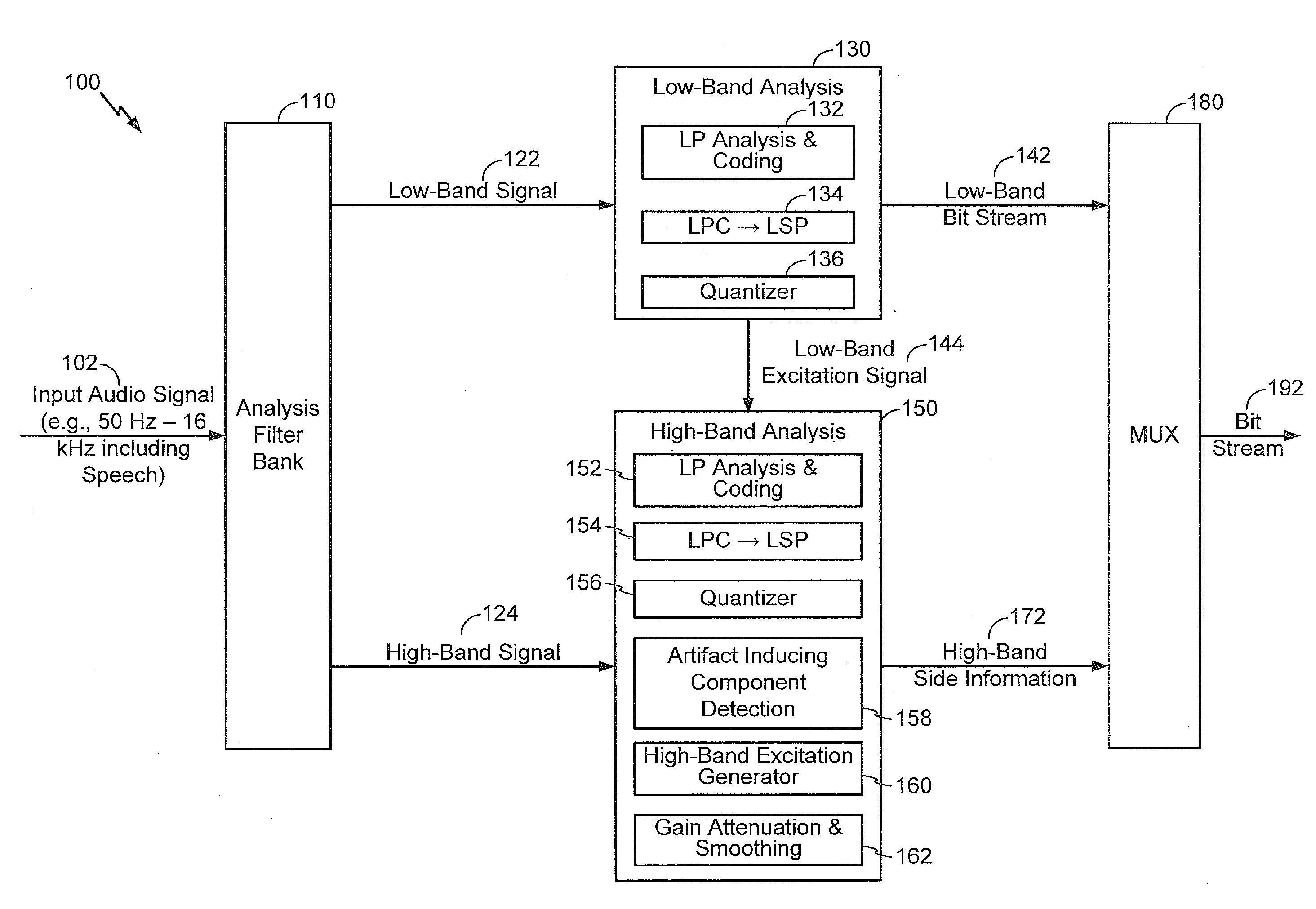
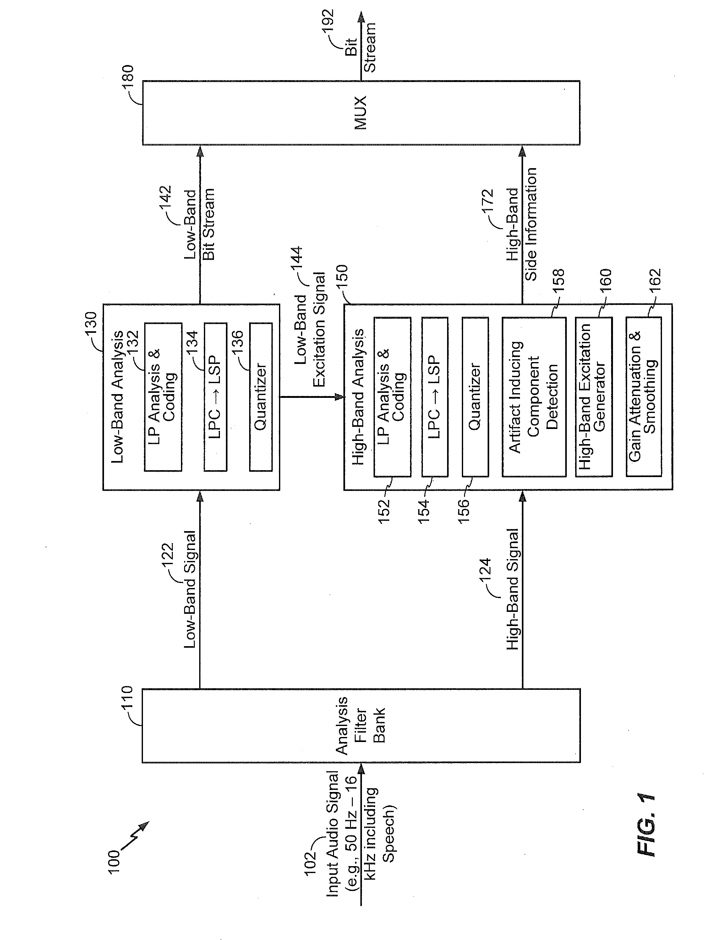
[0019]Referring to FIG. 1, a particular embodiment of a system that is operable to perform gain control is shown and generally designated 100. In a particular embodiment, the system 100 may be integrated into an encoding system or apparatus (e.g., in a wireless telephone or coder / decoder (CODEC)).

[0020]It should be noted that in the following description, various functions performed by the system 100 of FIG. 1 are described as being performed by certain components or modules. However, this division of components and modules is for illustration only. In an alternate embodiment, a function performed by a particular component or module may instead be divided amongst multiple components or modules. Moreover, in an alternate embodiment, two or more components or modules of FIG. 1 may be integrated into a single component or module. Each component or module illustrated in FIG. 1 may be implemented using hardware (e.g., a field-programmable gate array (FPGA) device, an application-specific...


PUM


Abstract

A particular method includes determining, based on an inter-line spectral pair (LSP) spacing corresponding to an audio signal, that the audio signal includes a component corresponding to an artifact-generating condition. The method also includes, in response to determining that the audio signal includes the component, adjusting a gain parameter corresponding to the audio signal. For example, the gain parameter may be adjusted via gain attenuation and / or gain smoothing.

Description

I. CROSS-REFERENCE TO RELATED APPLICATIONS[0001]The present application claims priority from commonly owned U.S. Provisional Patent Application No. 61 / 762,803 filed on Feb. 8, 2013, the content of which is expressly incorporated herein by reference in its entirety.II. FIELD[0002]The present disclosure is generally related to signal processing.III. DESCRIPTION OF RELATED ART[0003]Advances in technology have resulted in smaller and more powerful computing devices. For example, there currently exist a variety of portable personal computing devices, including wireless computing devices, such as portable wireless telephones, personal digital assistants (PDAs), and paging devices that are small, lightweight, and easily carried by users. More specifically, portable wireless telephones, such as cellular telephones and Internet Protocol (IP) telephones, can communicate voice and data packets over wireless networks. Further, many such wireless telephones include other types of devices that ar...

Claims


Application Information

Patent Timeline
IPC IPC(8): G10L19/03
CPCG10L19/03G10L21/0264G10L21/038
Inventor ATTI, VENKATRAMAN SRINIVASAKRISHNAN, VENKATESH
Owner QUALCOMM INC
Learn More