
System and method for the reconditioning of barrels including a robotic arm with a removable laser module

a technology of laser module and robotic arm, which is applied in the field of system and method for the reconditioning of barrels, can solve the problems of obscuring the optical path of the laser scanner, introducing problems, and damaging the mechanical and electronic components of the laser scanner

Inactive Publication Date: 2014-08-21
DIVERSE BARREL SOLUTIONS
View PDF6 Cites 10 Cited by
  • Summary
  • Abstract
  • Description
  • Claims
  • Application Information

AI Technical Summary

Benefits of technology

The invention is a system and method for reconditioning barrels using a robotic arm, a router assembly, and a laser assembly. The laser assembly is attached to the robot arm and can measure the inside profile of a barrel. A stand is used for attaching the laser assembly and a cover is moveable to cover the electrical contacts. Compressed air is directed to blow air over the external optical components of the laser assembly when it is within the stand. The system also includes a floor and a clamping mechanism for securing a barrel in a fixed position. The method involves scanning the inside profile of a barrel, detaching the laser assembly, and routing the inside of the barrel using the determined path. The laser scanner is cleaned with compressed air before scanning. The technical effect of the invention is to improve the efficiency and accuracy of reconditioning barrels by automating the process.

Problems solved by technology

Whilst this system ensures that the laser and the router are well aligned, having the laser co-located with the router whilst routing introduces problems.
The first problem being vibrations from the router damaging mechanical and electronic components of the laser scanner, in particular electromechanical components such as crystal oscillators.
The second problem being debris from the router obscuring the optical paths of the laser scanner.
This arrangement ensures that vibrations and debris from the router do not affect the laser scanner, however it introduces the problem of accurately aligning the laser scanner and the router.
The accuracy of the system is further compromised in that it is first required to locate the barrel with respect to the laser scanner and then with respect to the router.
Such a system also carries the cost and complexity of having two robotic arms.

Method used


Image

  • System and method for the reconditioning of barrels including a robotic arm with a removable laser module
  • System and method for the reconditioning of barrels including a robotic arm with a removable laser module
  • System and method for the reconditioning of barrels including a robotic arm with a removable laser module

Examples


Embodiment Construction

[0064]The following detailed description of the invention refers to the accompanying drawings. Wherever possible, the same reference numbers will be used throughout the drawings and the following description to refer to the same and like parts. Dimensions of certain parts shown in the drawings may have been modified and / or exaggerated for the purposes of clarity or illustration.

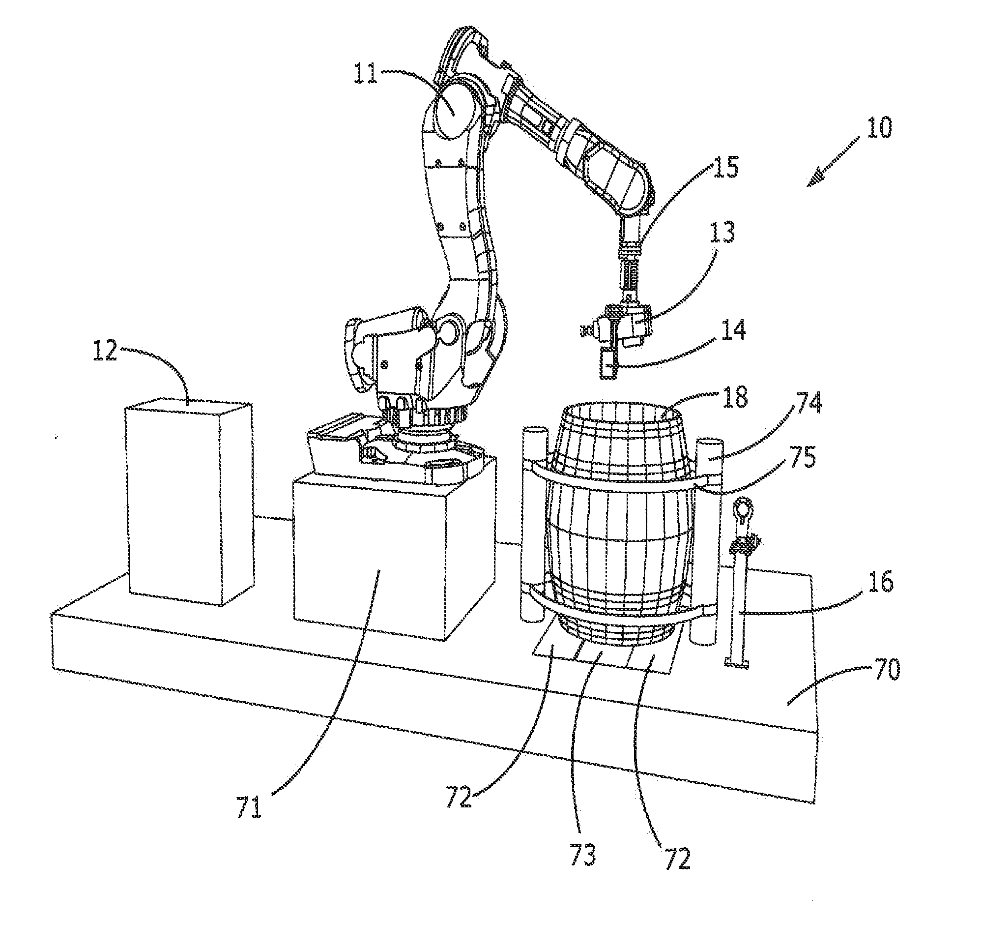
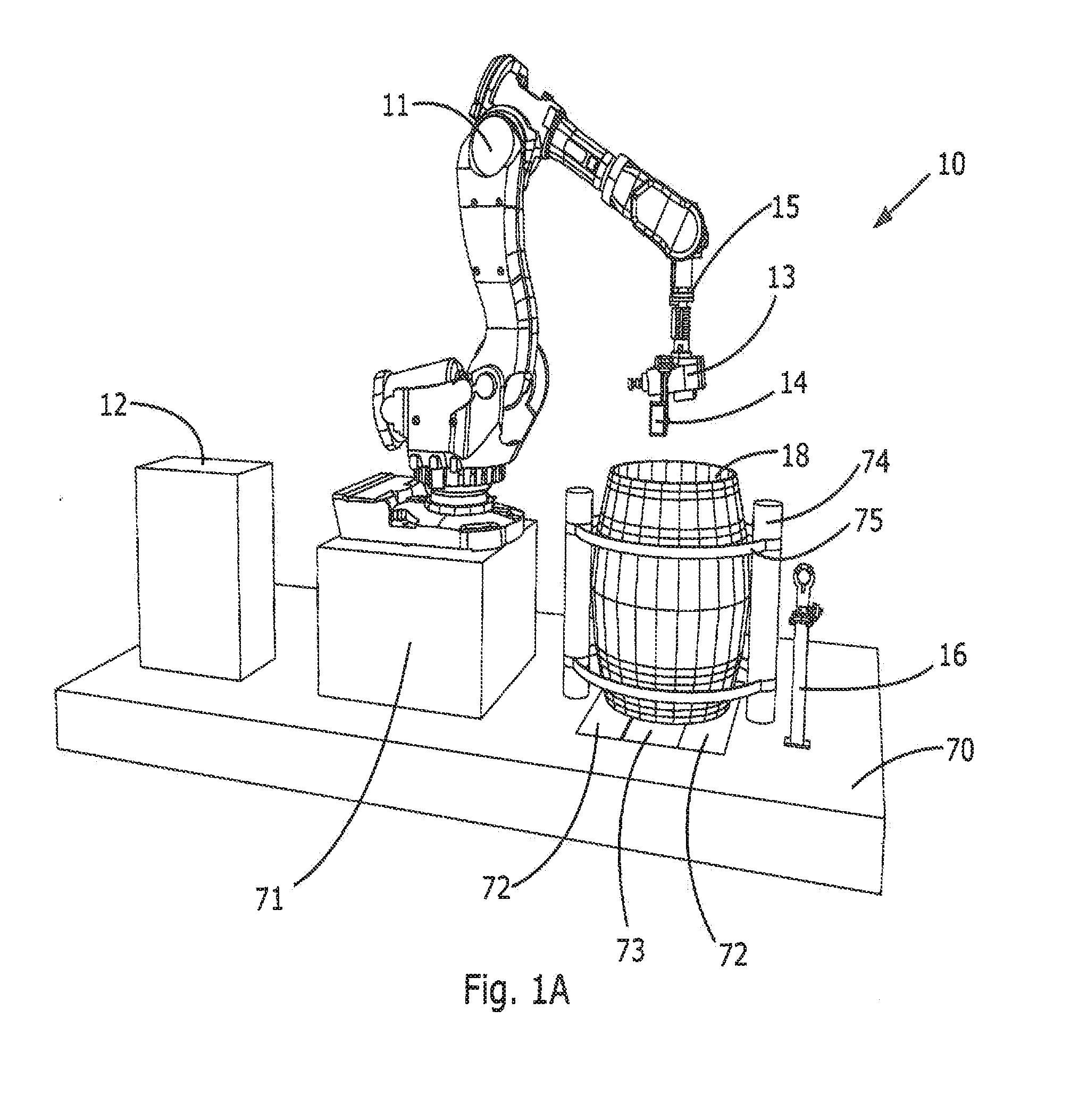
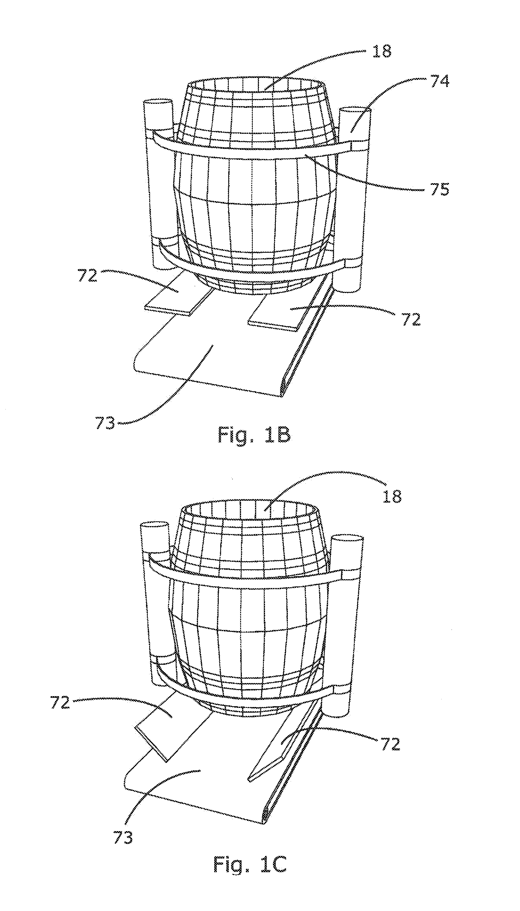
[0065]The present invention relates to a system 10 and method for reconditioning a barrel 18. As seen in FIG. 1A the main features of the barrel reconditioning system 10 are: a multi-axis robot arm 11 under the control of a control system 12; a router assembly 13 fixedly attached to the end of the robot arm 11; a laser assembly 14 removably attached to the router assembly 13 and a stand 16 for accepting the laser assembly 14.

[0066]The system 10 is mounted in an enclosure of which only the floor 70 is shown in the figures for the sake of clarity. The enclosure is sealed to allow the extraction of wood dust and...


PUM

PropertyMeasurementUnit
depthaaaaaaaaaa
electricalaaaaaaaaaa
trajectoryaaaaaaaaaa

Abstract

A system for reconditioning barrels comprising: a robot arm; a router assembly for routing the inside surface of a barrel; and a laser assembly for measuring the inside profile of a barrel, wherein: the router assembly is fixedly attached to the robot arm; and the laser assembly is removably attached to the router assembly thus allowing the laser assembly to be removed whilst the barrel is being routed in order to protect the laser from airborne particles and vibrations from the router.

Description

FIELD OF THE INVENTION[0001]This invention relates to a system and method for the reconditioning of barrels, in particular a system including a robotic arm with a removable laser module.BACKGROUND TO THE INVENTION[0002]Details of robotic systems for the reconditioning of barrels have been previously disclosed by the present applicant in for example International Applications PCT / AU2008 / 001684 and PCT / AU2011 / 000418. Whilst presenting an improvement over the prior art, further improvements to these systems are possible.[0003]The prior art systems incorporate a laser scanner for mapping the internal profile of a barrel and a router for removing a surface layer of the barrel; with the trajectory of the router being calculated from the measured profile of the barrel. Precise measurement and routing is required in order to optimally recondition a barrel, with the alignment of the laser and the router being critical.[0004]In a first prior art system the laser scanner and the router are bot...

Claims


Application Information

Patent Timeline
Patent Type & Authority Applications(United States)
IPC IPC(8): B27H5/08B27M3/00
CPCB27M3/00B27H5/08B08B9/0808B08B9/0821B23C3/00B23Q3/15536B23Q11/005B23Q11/0067B23Q11/08B23Q17/2452B23Q17/2471B25J11/005B25J11/0055B25J15/04B25J19/022B27C5/00B27H5/00G05B19/404Y10S901/09Y10S901/41Y10S901/47Y10T409/304088Y10T409/304424Y10T409/306944Y10T409/30756Y10T409/307672Y10T409/30868Y10T483/115Y10T483/13Y10T483/15Y10T483/17Y10T483/18
Inventor WATERMAN, BRECK DONALD
Owner DIVERSE BARREL SOLUTIONS
Learn More