Fluid-filled vibration damping device

a vibration damping and flue-filled technology, which is applied in the direction of shock absorbers, machine supports, mechanical equipment, etc., can solve the problems of affecting the effect of vibration damping, and affecting the performance of vibration damping, so as to prevent significant reduction in vibration damping performance, reduce the effect of pressure fluctuations in the pressure-receiving chamber and rapid increase the constant of dynamic springs

Active Publication Date: 2014-08-21
SUMITOMO RIKO CO LTD
View PDF2 Cites 8 Cited by
  • Summary
  • Abstract
  • Description
  • Claims
  • Application Information

AI Technical Summary

Benefits of technology

[0026]According to the seventh aspect, since the elastic buffer body is allowed to undergo deformation without being restrained by the wall of the housing space along the opening edges of the communication holes, the elastic buffer body is elastically deformed more aggressively with the windows substantially shut off, thus exerting the vibration damping effect based on the liquid-pressure absorption action more favorably.
[0027]According to the present invention, the striking noise generated by the movable member coming in contact with the wall inner surface of the housing space is reduced by the energy attenuation effect based on inner frictions and the like of the elastic buffer body because of the provision of the elastic buffer body th

Problems solved by technology

Using the fluid-filled vibration damping device, a vibration damping effect is effectively obtained against vibration of frequency to which the orifice passage is tuned based on the flow behavior of the fluid, while such an effective vibration damping effect can hardly be obtained against vibration of frequencies outside the tuning frequency.
Especially since the orifice passage is substantially shut off due to antiresonance when vibration with a frequency higher than the tuning frequency is inputted, a problem of degraded performance of vibration damping arises due to an increased dynamic spring constant.
However, in the fluid-filled vibration damping device provided with the liquid-pressure transmission mechanism described above, the striking noise generated by impact forces tends

Method used


Image

  • Fluid-filled vibration damping device
  • Fluid-filled vibration damping device
  • Fluid-filled vibration damping device

Examples


first embodiment

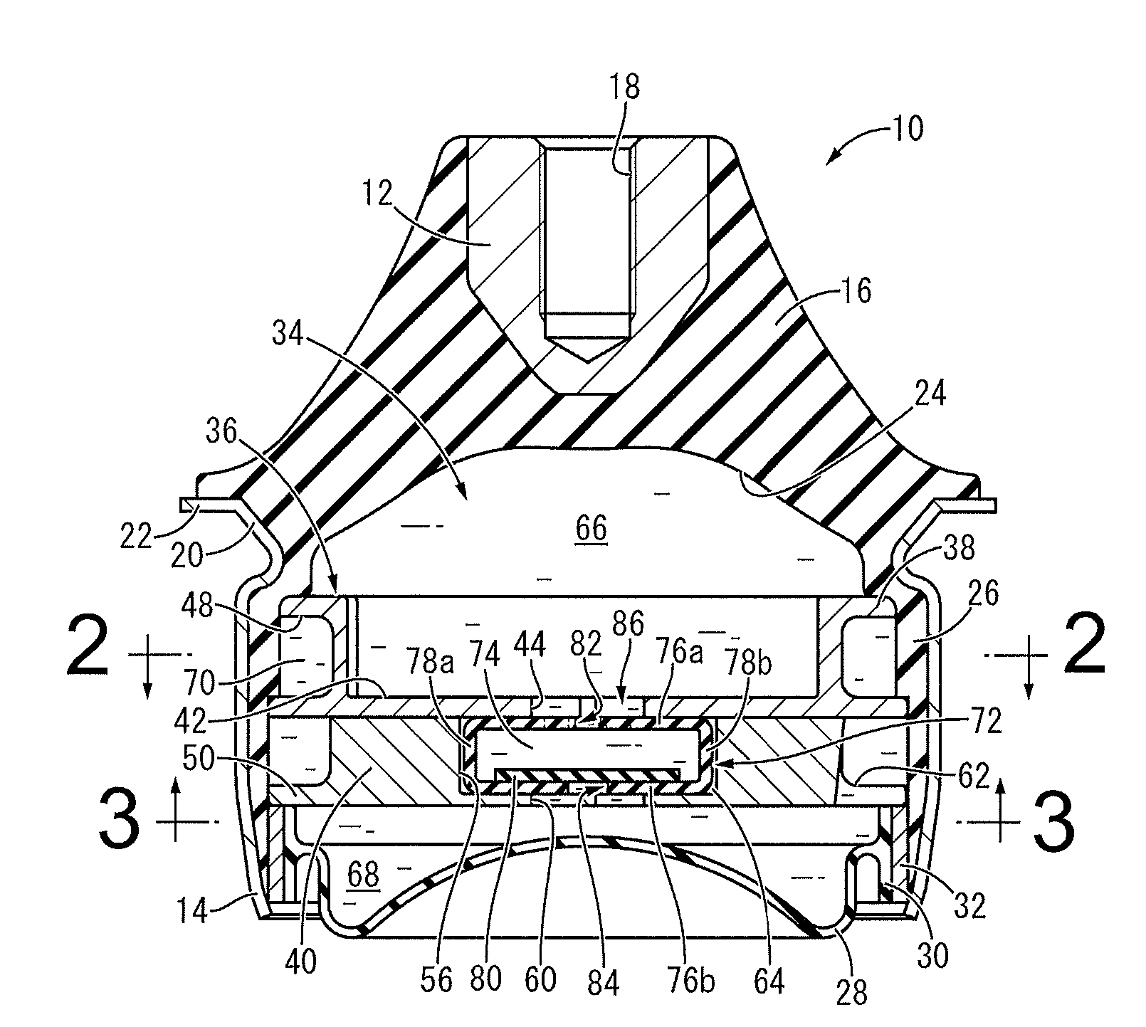
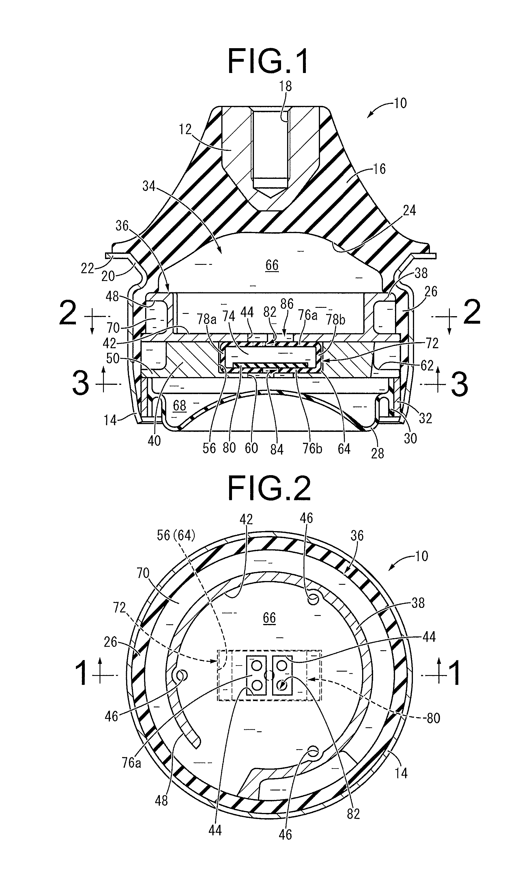
[0058]FIGS. 1 to 3 show an automotive engine mount 10 as the fluid-filled vibration damping device with the structure according to the present invention. The engine mount 10 has a structure where a first mounting member 12 and a second mounting member 14 are elastically connected by a main rubber elastic body 16, wherein the first mounting member 12 is mounted to an unillustrated power unit while the second mounting member 14 is mounted to an unillustrated vehicular body. In the following descriptions, the “up-down direction” generally means the up-down direction in FIG. 1.

[0059]More specifically, the first mounting member 12 is a high-rigidity member made of iron or aluminum alloy or the like in an approximate shape of a small-diameter circular block as a whole with its upper portion in an approximate shape of a cylinder and its lower portion in an approximate shape of a truncated cone inverted upside down gradually reducing its diameter downward. Also, on the first mounting member...

third embodiment

[0116]FIGS. 15 to 17 show a rubber buffer 110 as a band-like cylindrical body composing an engine mount as the fluid-filled vibration damping device with the structure according to the present invention.

[0117]The rubber buffer 110, as is the case with the rubber buffer 72 of the first embodiment, has a structure where the pair of facing plate portions 76a, 76b and the pair of side plate portions 78a, 78b are integrally provided, and is made in a hollow form with the inner space 74 therein.

[0118]Also, the rubber buffer 110 of the present embodiment has the facing plate portions 76a and 76b with a plurality of lightening holes 112 each formed thereon. The lightening holes 112 penetrate through both ends of the facing plate portions 76a, 76b in the longitudinal direction and are formed at locations away from the first and second windows 82, 84 in the longitudinal direction.

[0119]Then, the rubber buffer 110 is housed in the housing space 64 of the partition member 36, and the facing pla...

fourth embodiment

[0123]FIG. 18 shows an automotive engine mount 120 as the fluid-filled vibration damping device with a structure according to the present invention. The engine mount 120 has a partition member 122 that separates the pressure-receiving chamber 66 from the equilibrium chamber 68, and the partition member 122 is composed of the upper partition member 38 and the lower partition member 124.

[0124]As shown in FIG. 19, the lower partition member 124 is provided with the housing concave 56 at the center thereof in the radial direction, and the pair of second communication holes 60, 60 are formed vertically penetrating through the bottom wall of the housing concave 56. Also on the bottom wall of the housing concave 56, a concave portion 126 as a concave / convex portion is formed. The concave portion 126 is a shallow concavity with an approximately rectangular cross section opening to the top surface of the bottom wall of the housing concave 56. In addition, the concave portion 126 extends to t...


PUM


Abstract

A fluid-filled vibration damping device including an elastic buffer body supported by a partition member and arranged in a housing space such that at least one of wall inner surfaces of the housing space on sides of a pressure-receiving chamber and an equilibrium chamber is covered by the elastic buffer body. Windows are formed to penetrate the elastic buffer body at portions corresponding to communication holes formed in walls of the housing space so that the communication holes are narrowed by the windows of the elastic buffer body, and a ratio (a/l) of an opening area (a) of the windows to a penetration length (l) thereof is made smaller than a ratio (A/L) of an opening area (A) of the communication holes to a penetration length (L) thereof.

Description

INCORPORATED BY REFERENCE[0001]The disclosure of Japanese Patent Application No. 2012-017661 filed on Jan. 31, 2012 including the specification, drawings and abstract is incorporated herein by reference in its entirety. This is a Continuation of International Application No. PCT / JP2012 / 005409 filed on Aug. 28, 2012.BACKGROUND OF THE INVENTION[0002]1. Field of the Invention[0003]The present invention relates generally to a vibration damping device to be used, for example, for automotive engine mounts, body mounts, member mounts and the like, and more particularly, to a fluid-filled vibration damping device utilizing vibration damping effects based on the flow behavior of a fluid sealed therein.[0004]2. Description of the Related Art[0005]Conventionally, there has been known a fluid-filled vibration damping device as a vibration damping connecting body or a vibration damping supporting body interposed between the members constituting a vibration transmission system. The vibration damp...

Claims


Application Information

Patent Timeline
IPC IPC(8): F16F13/10
CPCF16F13/10F16F13/106F16F13/107
Inventor KANAYA, TOMOHIRO
Owner SUMITOMO RIKO CO LTD
Why Eureka
Try Eureka