Piezoelectric array employing integrated MEMS switches

a piezoelectric array and switch technology, applied in the field of piezoelectric arrays, can solve the problems of increasing the complexity of the pmut device array and/or the control of the transducer elements, incurring significant overhead off the array substrate, and addressing individual pmut devices within a 2d array

Active Publication Date: 2014-08-21
FUJIFILM DIMATIX
View PDF10 Cites 70 Cited by
  • Summary
  • Abstract
  • Description
  • Claims
  • Application Information

AI Technical Summary

Benefits of technology

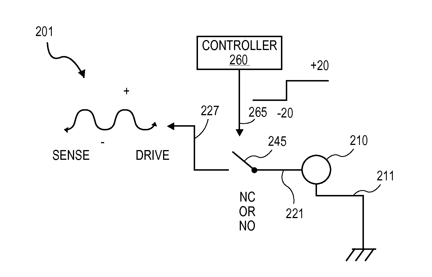
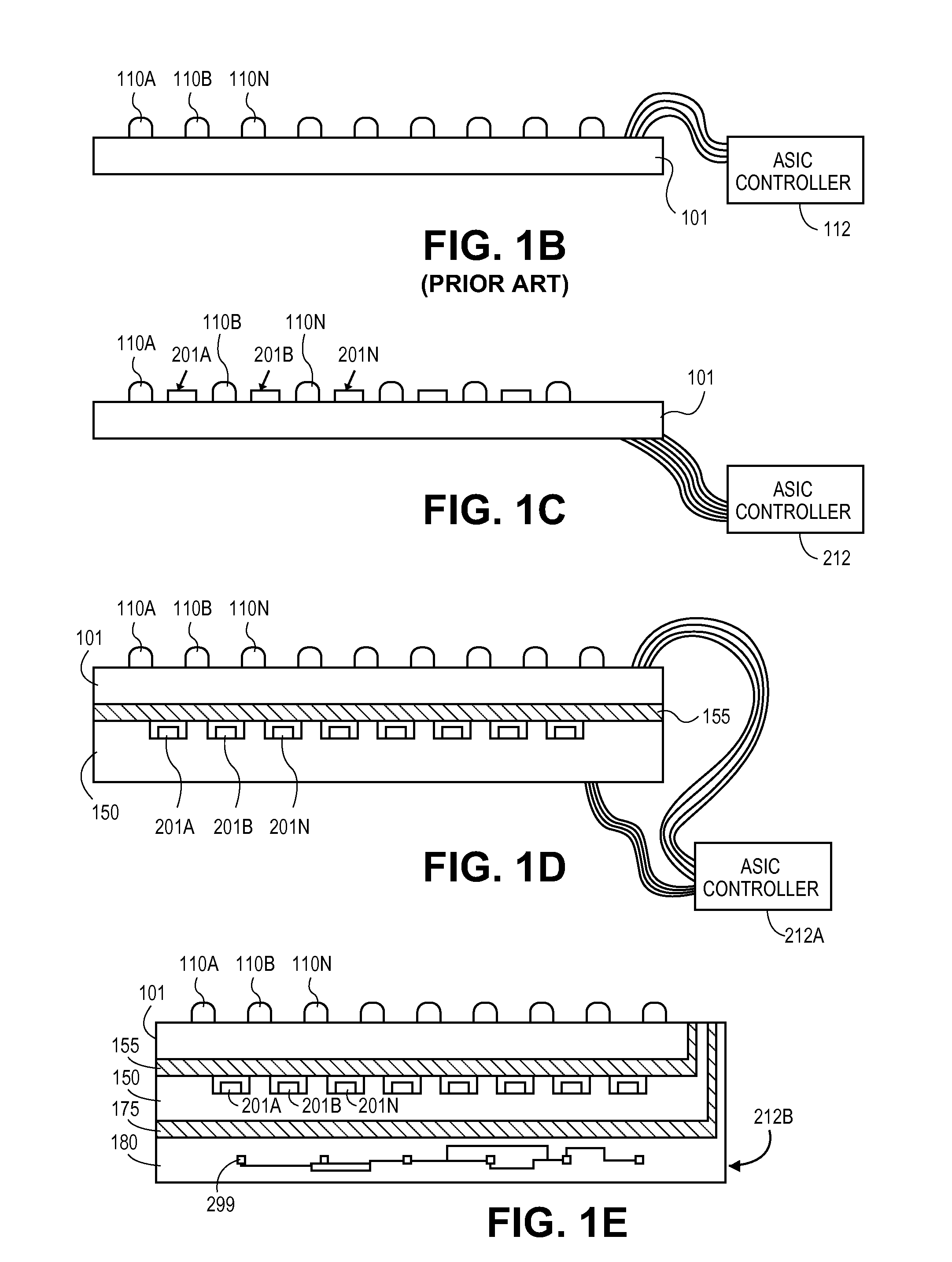
[0007]Switched micromachined transducer arrays are described herein. In an embodiment, a MicroElectroMechanical Systems (MEMS) switch, or relay, is integrated with a transducer element. The MEMS switch may be a series switch, as in a pass gate for example, or a shunt switch. In embodiments, the MEMS switch is implemented in the same substrate as the transducer array, or in a separate substrate bonded to that of the transducer array, to implement one or more logic gate, shift register, transducer control, or transducer element addressing

Problems solved by technology

However, addressing individual pMUT devices within a 2D array is technically challenging because the sheer number of channels scales rapidly, requiring complex device interconnection and multi-layered flex assemblies between the arrayed pMUT device (e.g., print head, ultrasonic transdu

Method used


Image

  • Piezoelectric array employing integrated MEMS switches
  • Piezoelectric array employing integrated MEMS switches
  • Piezoelectric array employing integrated MEMS switches

Examples


Embodiment Construction

[0028]In the following description, numerous details are set forth. It will be apparent, however, to one skilled in the art, that the present invention may be practiced without these specific details. In some instances, well-known methods and devices are shown in block diagram form, rather than in detail, to avoid obscuring the present invention. Reference throughout this specification to “an embodiment” or “in one embodiment” means that a particular feature, structure, function, or characteristic described in connection with the embodiment is included in at least one embodiment of the invention. Thus, the appearances of the phrase “in an embodiment” in various places throughout this specification are not necessarily referring to the same embodiment of the invention. Furthermore, the particular features, structures, functions, or characteristics may be combined in any suitable manner in one or more embodiments. For example, a first embodiment may be combined with a second embodiment...


PUM


Abstract

Switchable micromachined transducer arrays are described where a MicroElectroMechanical Systems (MEMS) switch, or relay, is monolithically integrated with a transducer element. In embodiments, the MEMS switch is implemented in the same substrate as the transducer array to implement one or more logic, addressing, or transducer control function. In embodiments, each transducer element of an array is a piezoelectric element coupled to at least one MEMS switch to provide element-level addressing within the array. In certain embodiments the same piezoelectric material employed in the transducer is utilized in the MEMS switch.

Description

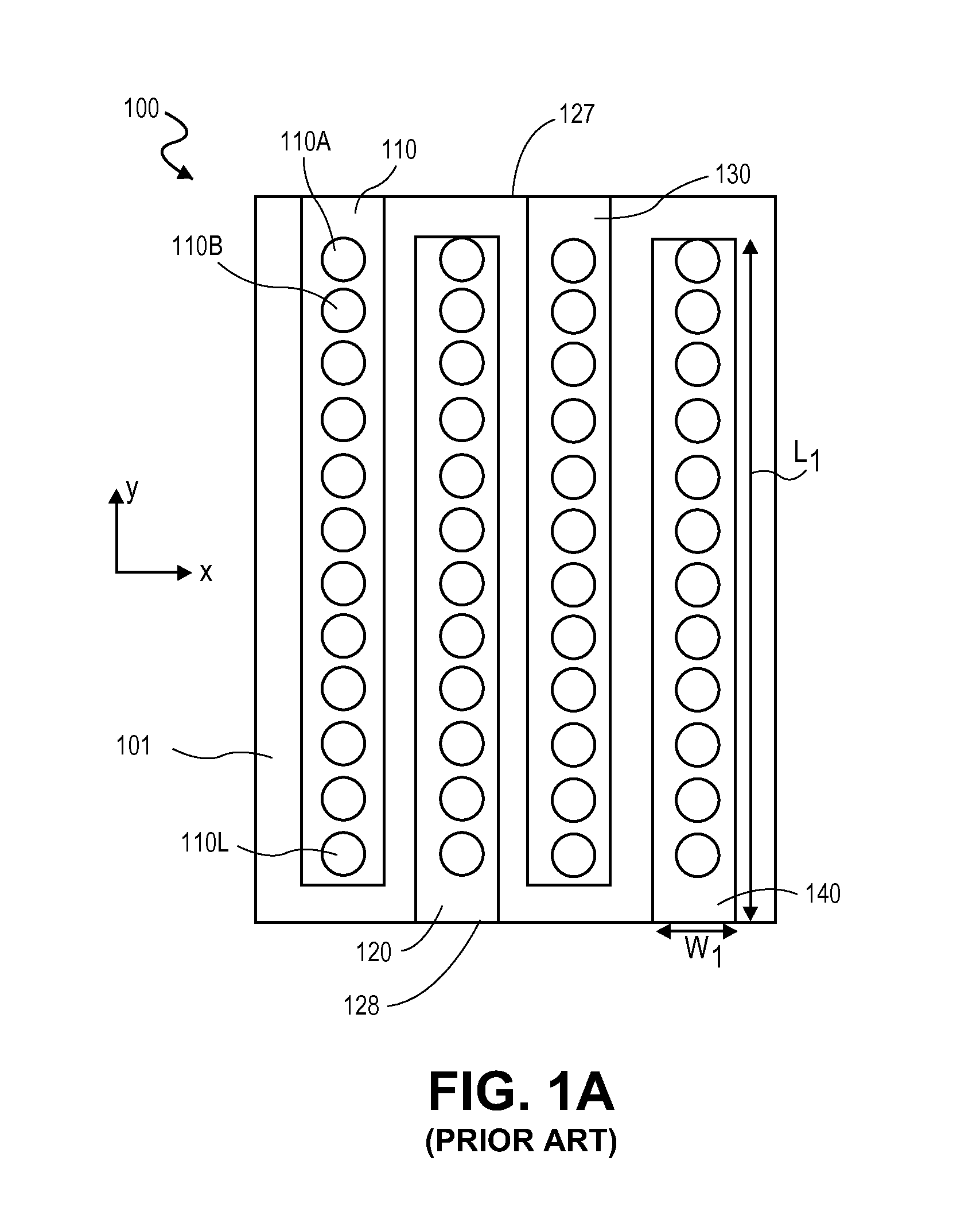
TECHNICAL FIELD[0001]Embodiments of the invention generally relate to arrays of piezoelectric transducers, and more specifically pertain to Microelectromechanical (MEM) switched 2D piezoelectric transducers arrays.BACKGROUND[0002]Transducer arrays are utilized in many applications. Print heads for inkjet or 3D printers are one widespread application, for example. Transducer arrays also find application in ultrasonic imaging. Transducer arrays often employ capacitive or piezoelectric transducer elements. Generally, a piezoelectric transducer element includes a piezoelectric membrane capable of mechanical deflection of the membrane in response to a time-varying driving voltage. For print heads, the membrane is driven to expel ink or other fluid in a controllable manner, for ultrasonic piezoelectric transducer devices the membrane is driven to generate a high frequency pressure wave in a propagation medium (e.g., air, water, or body tissue) in contact with an exposed outer surface of t...

Claims


Application Information

Patent Timeline
IPC IPC(8): B81B7/00H01L41/08H01L41/09B81B7/02
CPCB81B7/008H01L41/09H01L41/0825B81B7/02H01H1/0036G01N29/262G01S15/8925G01S7/52017B06B1/0207B06B1/0629B06B2201/20G10K11/346H10N39/00H10N30/2047H10N30/1071
Inventor HAJATI, ARMAN
Owner FUJIFILM DIMATIX
Why Eureka
Try Eureka