
Method and device for data transmission

a data transmission and data technology, applied in the field of wireless communication, can solve the problems of reducing the complexity of network maintenance and the cost of device upgrading, degrading the efficiency of the system, etc., and achieve the effect of lowering the signaling overhead of the system

Inactive Publication Date: 2014-08-21
CHINA ACAD OF TELECOMM TECH
View PDF5 Cites 57 Cited by
  • Summary
  • Abstract
  • Description
  • Claims
  • Application Information

AI Technical Summary

Benefits of technology

This invention provides a way for a network to send data to a device without needing to establish a connection. This reduces signaling overhead and makes the system more efficient. The device detects a specific signal and transmits data without needing to connect. This results in a reduction of signaling overhead and improved efficiency for the network.

Problems solved by technology

Due to lowered coupling of the control signaling with the user data, the emergence of the new service only requires the network element responsible for the user plane bearer to be upgraded without influencing transmission of the control information, thus greatly lowering the complexity of network maintenance and the cost of device upgrading.
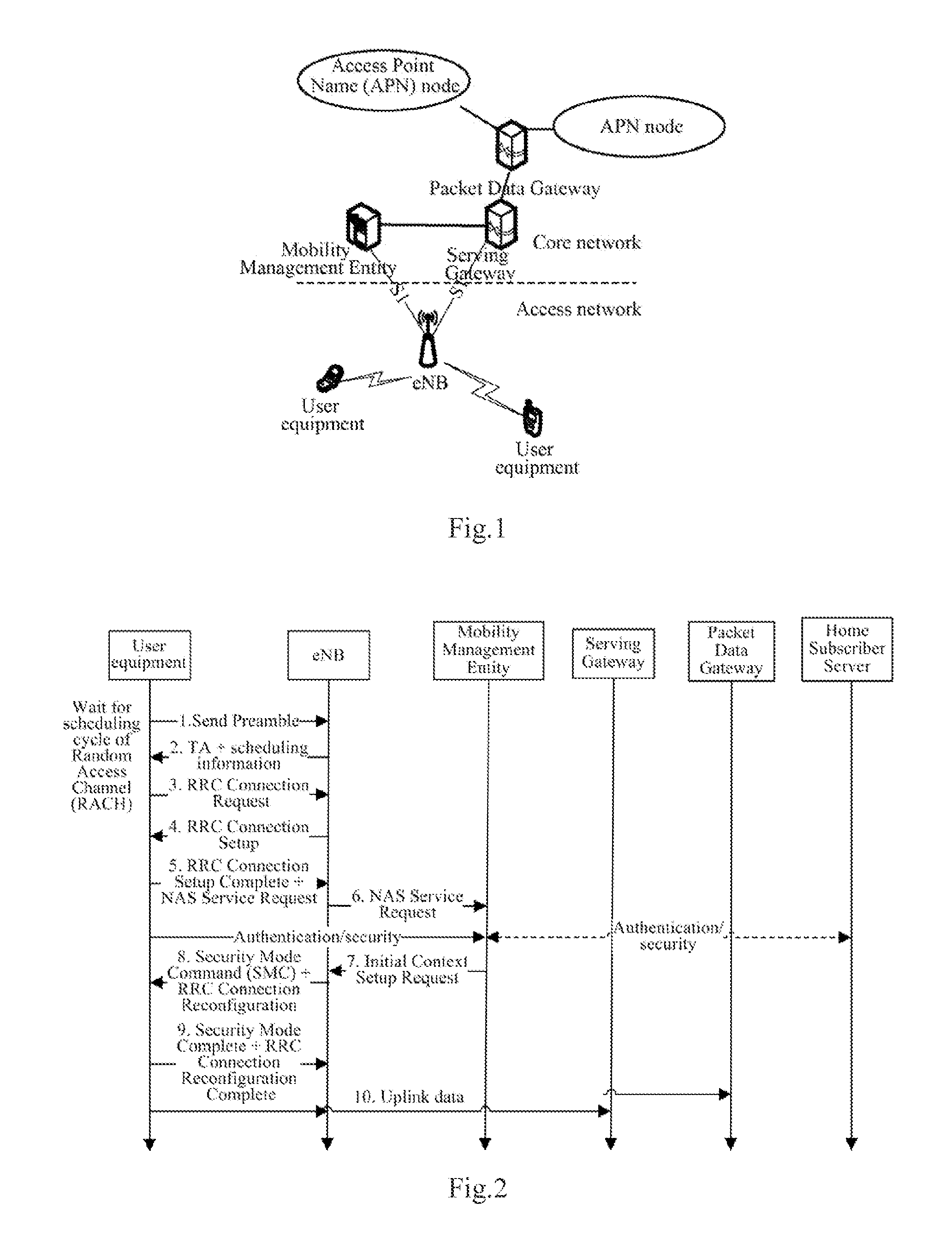
However in order to transmit such data, the network side and the MTC user equipment can transmit the data over a DRB / RB and an S1 / Iu bearer only after establishing the DRB / RB and the S1 / Iu bearer in the signaling flow as illustrated in FIG. 2 in the existing data transmission solution, but there is a considerable overhead of the signaling flow as illustrated in FIG. 2, thus degrading the efficiency of the system.

Method used


Image

  • Method and device for data transmission
  • Method and device for data transmission
  • Method and device for data transmission

Examples


first embodiment

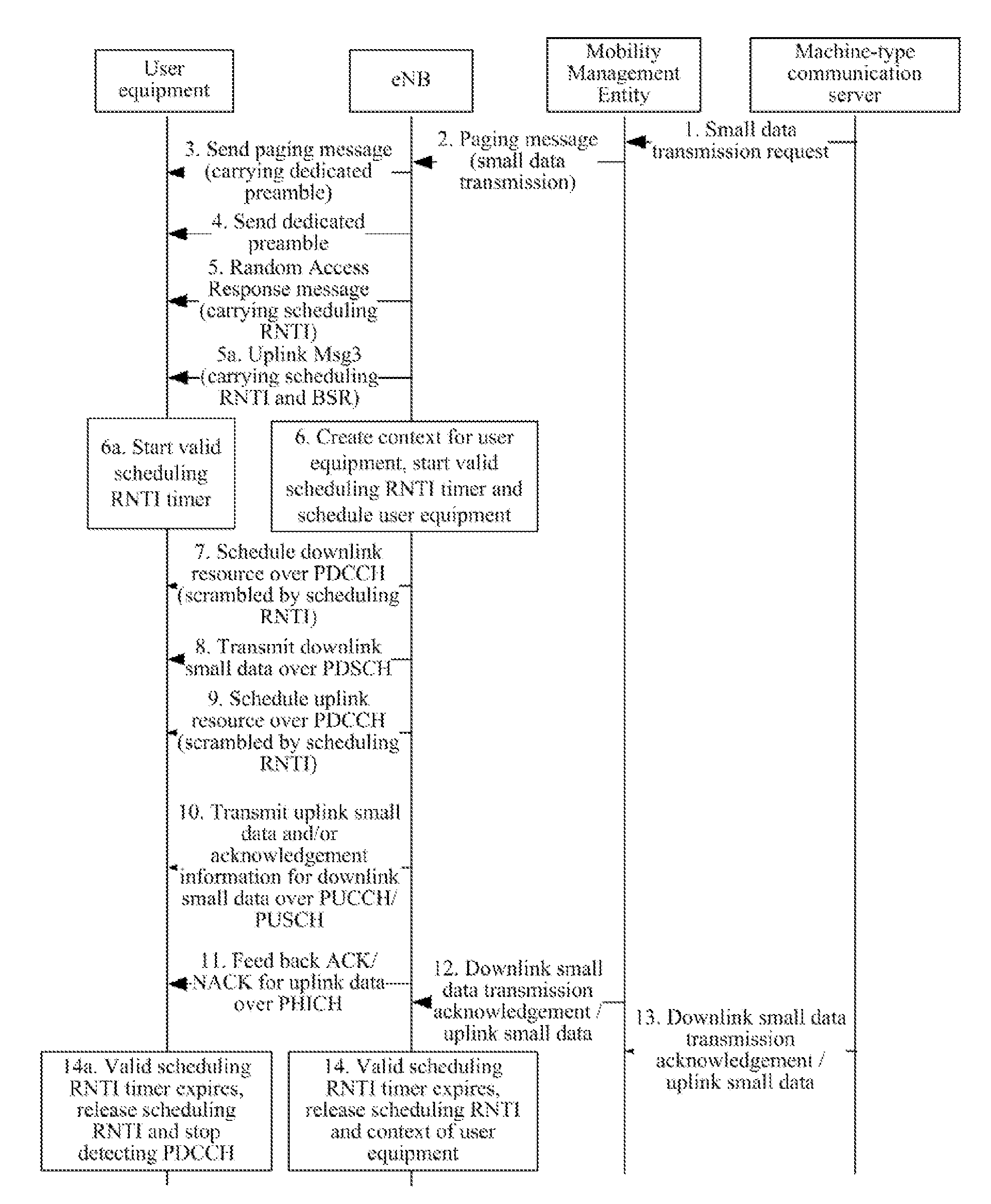
[0095]This embodiment relates to a flow with a dedicated preamble carried in a paging message as illustrated in FIG. 5A.

[0096]Step 1: The network side (e.g., an MTC server) with a small amount of small data to be transmitted to a UE sends a small data transmission request carrying the small data to an MME.

[0097]Step 2: The MME sends the small data and an identifier S-TMSI of the UE to a relevant eNB in a paging message, where the paging message may further carry small data transmission characteristic information to notify the eNB that the current data transmission needs to be performed in a data transmission mode without establishing an RRC connection.

[0098]Step 3: The eNB stores the relevant information and pages the user equipment by a paging message carrying a dedicated preamble.

[0099]Step 4: The user equipment initiates a random access using the dedicated preamble, that is, sends an Msg1.

[0100]Step 5: The eNB returns a random access response message (i.e., an Msg2) to the user e...

second embodiment

[0122]This embodiment relates to a flow with a scheduling RNTI carried in a paging message as illustrated in FIG. 5B.

[0123]The other steps than the step 3 to the step 6 are the same as in the first embodiment, and a repeated description thereof will be omitted here.

[0124]Step 3: The eNB stores the relevant information and pages the user equipment by a paging message carrying a scheduling RNTI.

[0125]Step 4: The user equipment initiates a random access using a contention random access preamble, that is, sends an Msg1.

[0126]Step 5: The eNB returns a random access response message (i.e., an Msg2) to the user equipment, where the Msg2 carries an uplink TA and an allocated C-RNTI.

[0127]Step 5a: The user equipment sends the scheduling RNTI to the eNB in an Msg3 upon reception of the Msg2, and if there is uplink data to be transmitted, then the Msg3 may carry an BSR.

[0128]Step 6: The eNB releases the RNTI carried in the step 5 correspondingly over an uplink resource over which the Msg3 is r...


PUM


Abstract

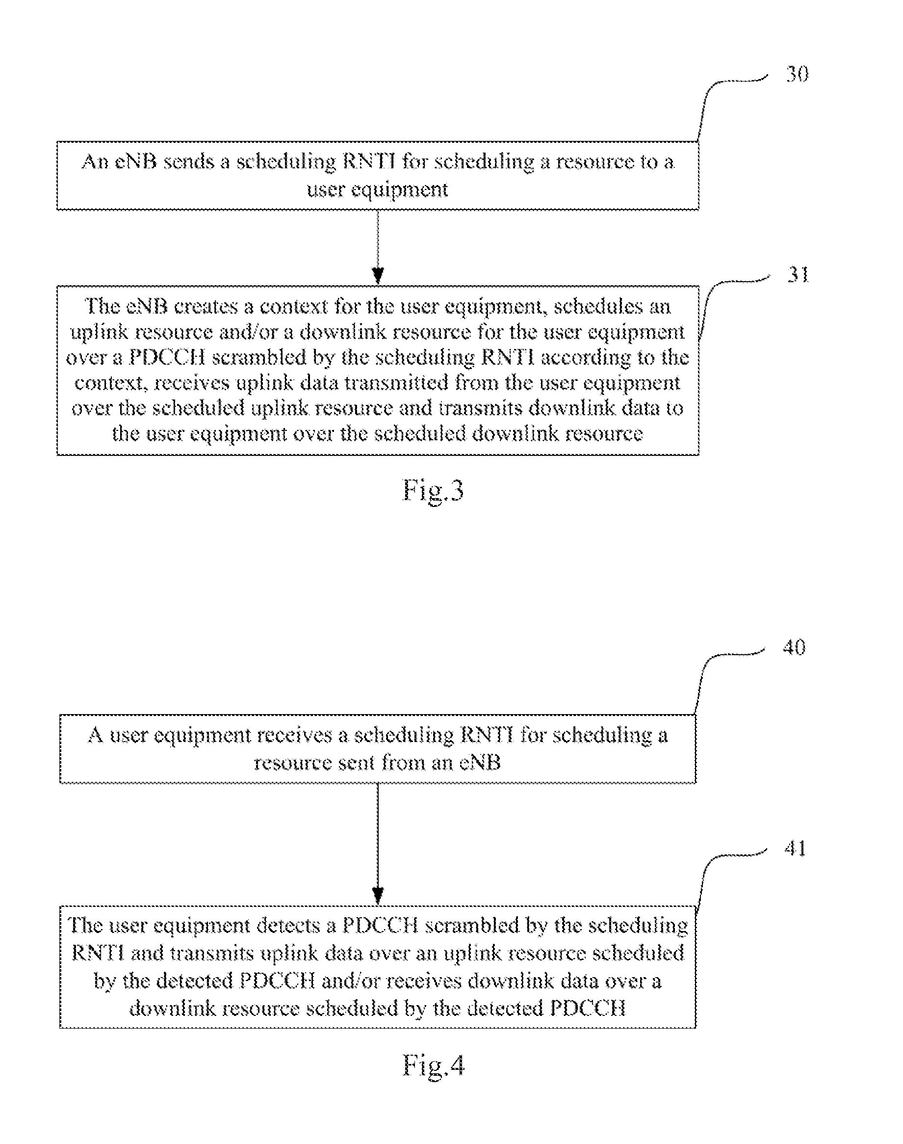
Disclosed are a method and a device for data transmission, which relate to the field of wireless communication technologies, and are used for decreasing signaling overhead of a system in this application, an eNB delivers a scheduling radio network temporary identifier RNTI to a terminal; the eNB schedules uplink resources and / or downlink resources for the terminal through a physical downlink control channel PDCCH scrambled by using the scheduling RNTI, receives uplink data sent by the terminal on the scheduled uplink resources, and sends downlink data to the terminal on the scheduled downlink resources. The terminal monitors the PDCCH scrambled by using the scheduling RNTI, and sends the uplink data and / or receives the downlink data by using the resources scheduled by the monitored PDCCH. The method of this application can be used to effectively decrease the signaling overhead of the system.

Description

[0001]The present application claims priority to Chinese Patent Application No. 201110240607.3, filed with the Chinese Patent Office on Aug. 19, 2011 and entitled “Method and device for transmitting data”, which is hereby incorporated by reference in its entirety.FIELD OF THE INVENTION[0002]The present invention relates to the field of wireless communications and particularly to a method and device for transmitting data.BACKGROUND OF THE INVENTION[0003]FIG. 1 illustrates a network architecture of a Long Term Evolution (LTE) system including an Access Point Name (APN) node, a Packet Data Network GW (P-GW), a Serving Gateway (S-GW), a Mobility Management Entity (MME), an evolved Node B (eNB) and a User Equipment (UE).[0004]In order to facilitate deployment of a new service, the LTE system adopts a design scheme in which a user plane and a control plane are separated so that separate network elements (i.e., the MME and the S-GW) are responsible for control plane signaling and a user pl...

Claims


Application Information

Patent Timeline
IPC IPC(8): H04W4/00H04W72/04
CPCH04W4/005H04W72/0413H04W72/0446H04W68/00H04W72/12H04W72/21
Inventor ZHANG, HUIYINGQUAN, HAIYANGRUAN, HANG
Owner CHINA ACAD OF TELECOMM TECH
Learn More