Packaged Microphone with Frame Having Die Mounting Concavity

a technology of concave mounting and microphone, applied in the field of acoustic devices, can solve the problems of increasing fabrication costs and challenging interconnection of microphones with other components, and achieve the effect of effective electrical connection

Active Publication Date: 2014-08-21
INVENSENSE
View PDF2 Cites 15 Cited by
  • Summary
  • Abstract
  • Description
  • Claims
  • Application Information

AI Technical Summary

Benefits of technology

[0007]To make an effective electrical connection, the packaged microphone may have a bump or ball electrically connecting the microphone die to the substrate. In addition, or alternatively, the substrate may have an external surface mountable pad that is electrically connected with the microphone die.
[0008]In accordance with another embodiment, a packaged microphone has a molded cover and a molded frame secured to the cover. The frame and cover together form a lid structure. The frame has a frame surface with a concavity having a microphone die secured within it. The packaged microphone also has a substrate coupled with the lid structure and electrically connected with the microphone die. The substrate and lid structure together form a package having an interior volume containing the microphone die within the concavity. At least one of a bump and ball electrically connects the substrate with the microphone die. The packaged microphone further has an aperture through the package, and a seal proximate to the microphone die. The seal acoustically seals the microphone and the aperture to form a front volume and a back volume within the interior volume.
[0009]In accordance with other embodiments of the invention, a method of forming a packaged microphone secures an array of covers to an array of molded frames to form an array of assemblies. Each frame has a surface forming a concavity. The method mounts a plurality of microphone dies within a plurality of the concavities in the array of molded frames. To that end, each of the plurality of concavities has no more than one microphone die. In addition, the method secures an array of substrates to the array of assemblies to form an array of packages that each have interior volumes. Each package has a seal that forms a back volume and a front volume within the interior volume. Finally, the method cuts the array of packages to form individual packages.

Problems solved by technology

Interconnection of the microphone with other components can be challenging.
Flip chip interconnections, for example, often require expensive specialized equipment that ultimately increases fabrication costs.

Method used


Image

  • Packaged Microphone with Frame Having Die Mounting Concavity
  • Packaged Microphone with Frame Having Die Mounting Concavity
  • Packaged Microphone with Frame Having Die Mounting Concavity

Examples


Embodiment Construction

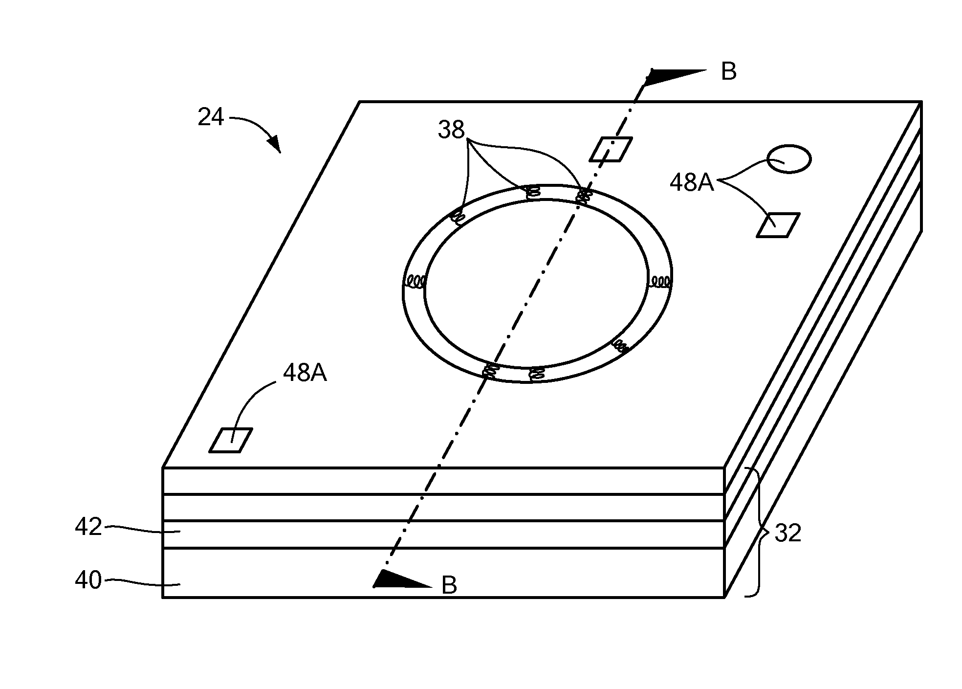
[0043]In illustrative embodiments, the package of a packaged microphone (also referred to as a “microphone system”) has a lid structure that significantly improves fabrication efficiencies, while facilitating electrical interconnection of internal components, such as MEMS microphones and other integrated circuits. To that end, the lid structure has a concavity for mounting a microphone die in a manner that permits relatively easy electrical interconnection with an underlying package base. In addition, existing fabrication processes can process the lid structure in panel form, permitting low cost batch processing. Details of a number of illustrative embodiments are discussed below.

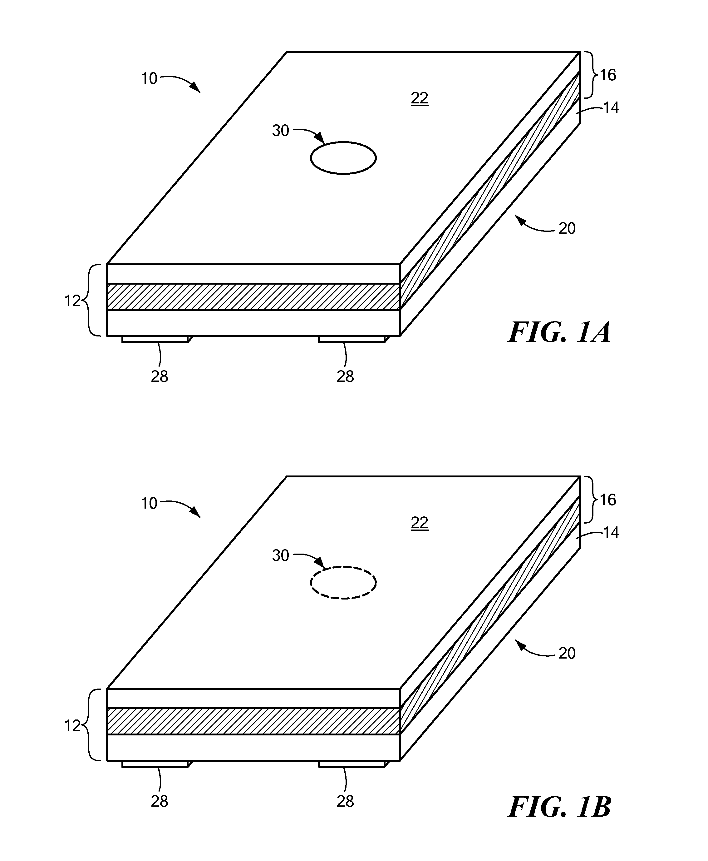
[0044]FIGS. 1A and 1B schematically show a packaged microphone system 10 (as noted above, also referred to as a “microphone system 10” or “packaged microphone 10”) implemented in accordance with illustrative embodiments of the invention. The packaged microphone 10 has a package 12 that may be coupled with a...


PUM


Abstract

A packaged microphone has a lid structure with an inner surface having a concavity, and a microphone die secured within the concavity. The packaged microphone also has a substrate coupled with the lid structure to form a package having an interior volume containing the microphone die. The substrate is electrically connected with the microphone die. In addition, the packaged microphone also has aperture formed through the package, and a seal proximate to the microphone die. The seal acoustically seals the microphone and the aperture to form a front volume and a back volume within the interior volume. The aperture is in acoustic communication with the front volume.

Description

FIELD OF THE INVENTION[0001]The invention generally relates to acoustic devices and, more particularly, the invention relates to MEMS acoustic devices and packaging of MEMS acoustic devices.BACKGROUND OF THE INVENTION[0002]MEMS microphones typically are secured within an interior chamber of a package to protect them from the environment. An integrated circuit chip, also mounted within the interior chamber and having active circuit elements, processes electrical signals to and from the microphone. One or more apertures through some portion of the package permit acoustic signals to reach the microphone. Receipt of the audio signal causes the microphone, with its corresponding integrated circuit chip, to produce an electronic signal representing the audio qualities of the received signal.[0003]Interconnection of the microphone with other components can be challenging. Flip chip interconnections, for example, often require expensive specialized equipment that ultimately increases fabric...

Claims


Application Information

Patent Timeline
Patent Type & Authority Applications(United States)
IPC IPC(8): H04R1/08
CPCH04R1/083H04R1/04H04R2201/003H04R2201/029H04R1/08H04R1/222H04R1/2892H04R19/005H04R19/04H04R31/006H04R2410/03
Inventor BOLOGNIA, DAVIDHARNEY, KIERAN P.
Owner INVENSENSE
Why Eureka
Try Eureka