Method and control unit for recognizing a weather condition in the surroundings of a vehicle

a technology for recognizing weather conditions and surrounding objects, applied in the field of recognizing weather conditions in the surroundings of vehicles, can solve the problems of only being able to react, system failure only being able to recognize weather conditions, so as to achieve rapid and efficient achievement, improve vehicle safety, and improve reliability.

Active Publication Date: 2014-08-21
ROBERT BOSCH GMBH
View PDF18 Cites 22 Cited by
  • Summary
  • Abstract
  • Description
  • Claims
  • Application Information

AI Technical Summary

Benefits of technology

[0015]In another specific embodiment, the light effect may represent at least one ground brightness, and a light distribution of the ground brightness may be ascertained from the imaging feature in the ascertainment step. In addition, the light distribution may be compared to an expected value of the light distribution in the determination step. A ground brightness may be understood to mean a brightness of the road which is perceivable from the vehicle. A light distribution may represent a perceivable distribution of light and dark locations on the roadway. For example, when the roadway is wet, only a small portion of the emitted light may be reflected back to the vehicle. A remainder of the emitted light which is directed from the wet roadway by total reflection may be reflected away from the vehicle. For a snow-covered roadway, a large portion of the emitted light may be diffusely reflected back to the vehicle over a large surface area. For a dry roadway, a moderate portion of the emitted light may be reflected back to the vehicle. For an oncoming vehicle the relationships may be reversed, since during rain the light that is reflected away by the oncoming vehicle as total reflection, corresponding to a direct headlight beam, may strike the host vehicle. In snow, the light may be diffusely reflected over a large surface area. An expected value of the light distribution may be an empirical value which represents an expected light distribution of the ground brightness under a certain weather condition. A road condition ahead of the vehicle may thus be detected as a particularly safety-relevant parameter, and corrective interventions by safety and comfort/convenience systems may be adapted and the driver of the vehicle may be made aware of same.
[0016]In an additional specific embodiment of the present invention, the light effect may represent at least one brightness in a lateral area near the ground, the lateral area being situated to the side of the vehicle, outside an area directly illuminated by headlights of the vehicle. A lateral area brightness value of the brightness may be ascertained from the imaging feature in the ascertainment step, and in addition the lateral area brightness value may be compared to an expected value of the lateral area brightness value in the determination step. A lateral area near the ground may be understood, for example, to mean a lane of the road adjacent to the lane of the host vehicle. Likewise, a lateral area near the ground may be understood to mean a soft shoulder or a hard shoulder of the road. The lateral area near the ground may be soiled, for example. Likewise, the lateral area near the ground may have accumulated snow. A lateral area brightness value may represent a brightness which is reflected from the lateral area. It may thus be recognized, for example, whether the roadway is soiled or covered with snow next to the lane of the host vehicle. An expected value of the lateral area brightness value may be an...

Problems solved by technology

In darkness, when the senses of the driver are already limited depending on the situation, timely recognition of weather conditions is problematic.
Therefore, these systems a...

Method used


Image

  • Method and control unit for recognizing a weather condition in the surroundings of a vehicle
  • Method and control unit for recognizing a weather condition in the surroundings of a vehicle
  • Method and control unit for recognizing a weather condition in the surroundings of a vehicle

Examples


Embodiment Construction

[0026]In the following description of preferred exemplary embodiments of the present invention, the same or similar reference numerals are used for the elements which are illustrated in the various figures and which have a similar action; a repeated description of these elements is dispensed with.

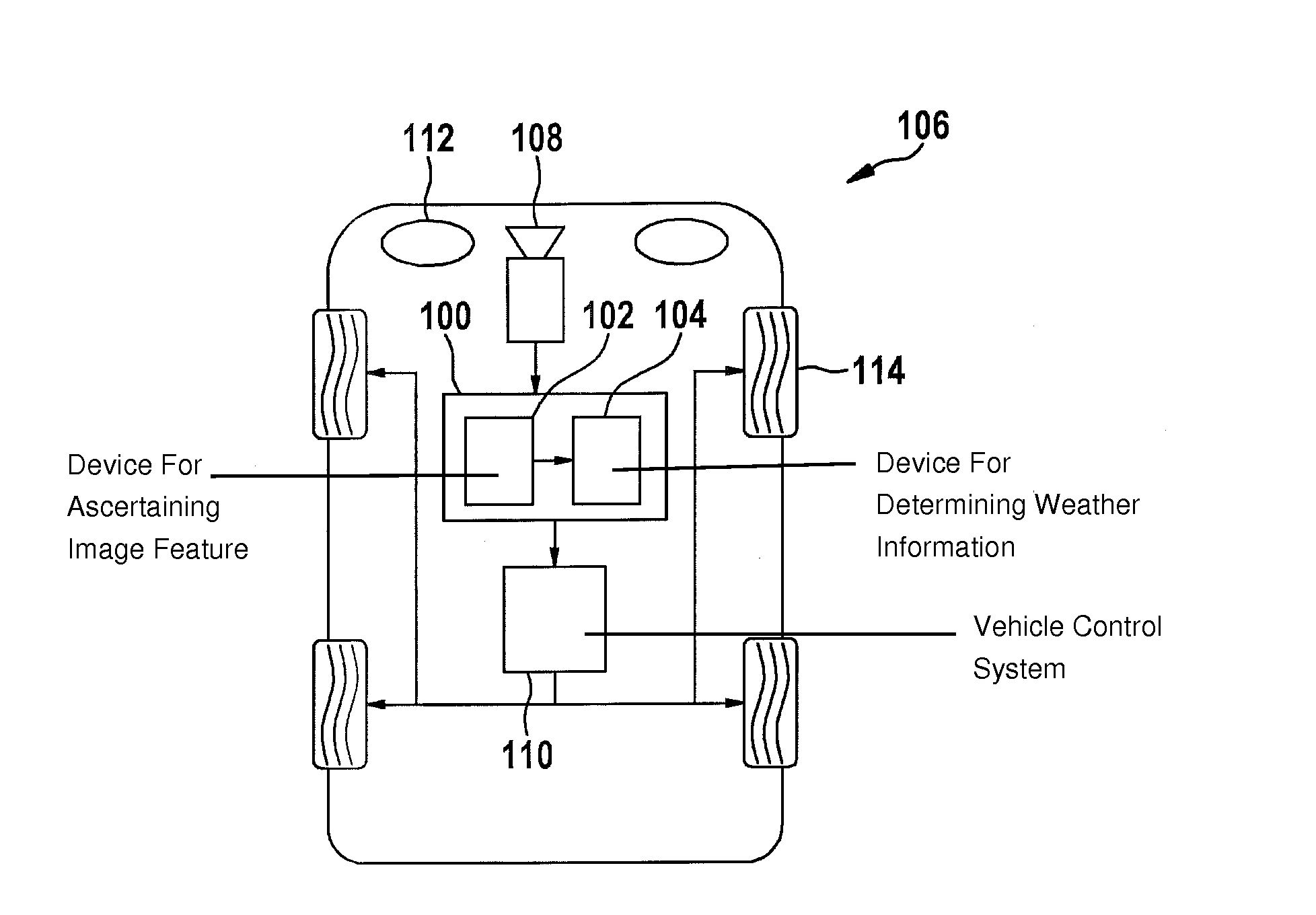
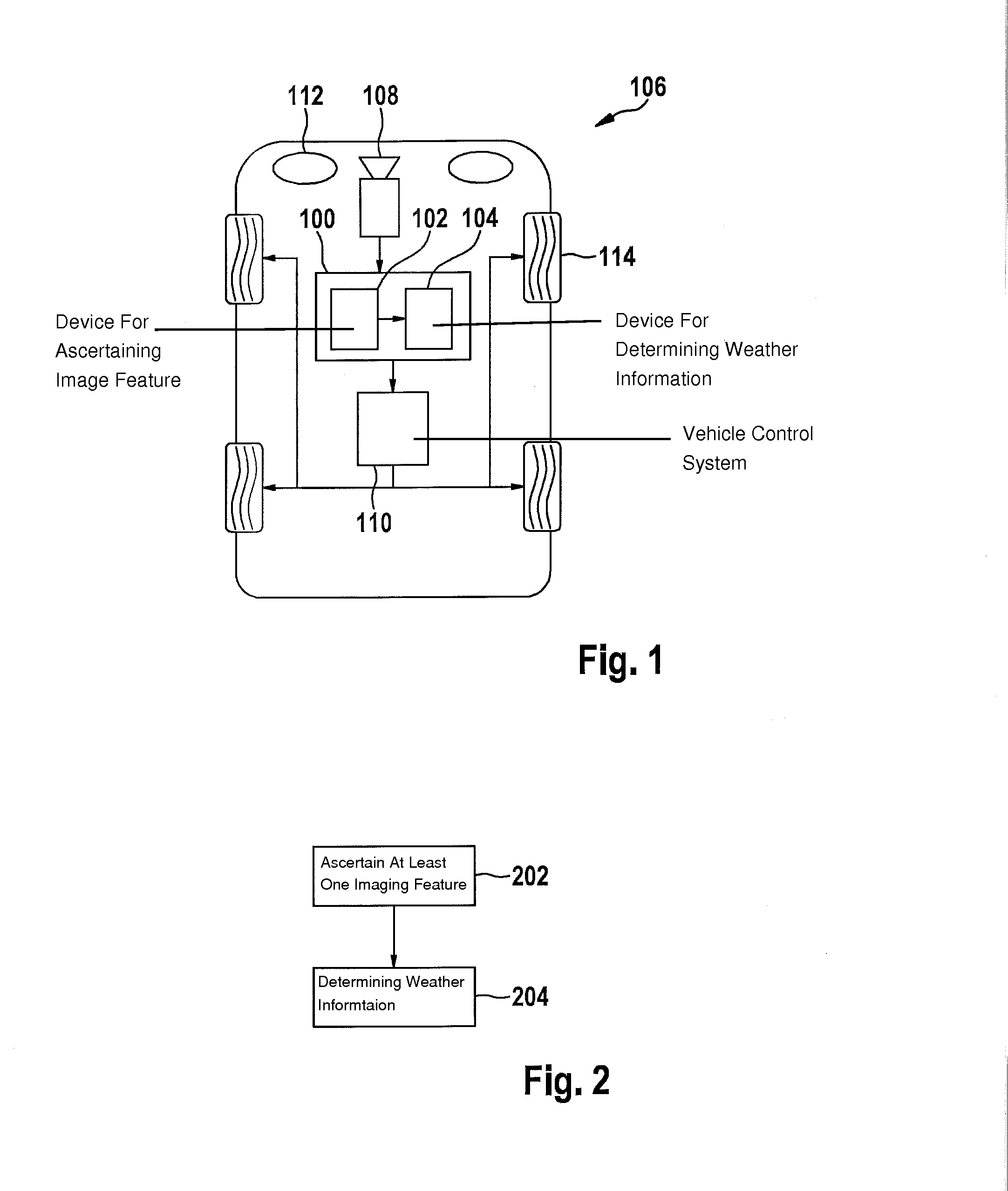
[0027]FIG. 1 shows an illustration of a vehicle having a control unit 100 for recognizing a weather condition in the surroundings of a vehicle according to one exemplary embodiment of the present invention. Control unit 100 has a device 102 for ascertaining an imaging feature in a piece of image information, and a device 104 for determining weather information for characterizing the weather condition. Vehicle 106 has a surroundings detection device 108 as well as a vehicle control system 110. In addition, vehicle 106 has two headlights 112 for illuminating a portion of the surroundings ahead of vehicle 106.

[0028]Surroundings detection device 108 is designed to detect at least the portion of...


PUM


Abstract

A method for recognizing a weather condition in the surroundings of a vehicle. The method includes a step of ascertaining at least one imaging feature in image information. The image information represents a depiction of at least a portion of the surroundings, and the imaging feature represents a light effect on a reflective or luminescent object in the portion of the surroundings. In addition, the method includes a step of determining weather information for characterizing the weather condition based on a comparison between the imaging feature and at least one expected value.

Description

FIELD OF THE INVENTION [0001]The present invention relates to a method for recognizing a weather condition in the surroundings of a vehicle, a control unit for recognizing a weather condition in the surroundings of a vehicle, and a corresponding computer program product.BACKGROUND INFORMATION [0002]For camera-based hardware and software systems in a vehicle, it is of interest to know the current prevailing weather conditions such as rain, snow, wet roads, fog, water spray, dust, etc.[0003]To this end, German Published Patent Appln. No. 10 2007 062 258 describes an optical rain sensor device for a motor vehicle.SUMMARY [0004]Against this background, the present invention presents a method for recognizing a weather condition in the surroundings of a vehicle, a control unit for recognizing a weather condition in the surroundings of a vehicle, and a corresponding computer program product.[0005]Weather conditions in the surroundings of a vehicle, in particular on a roadway ahead of the v...

Claims


Application Information

Patent Timeline
IPC IPC(8): G06K9/00
CPCG06K9/00791G01W1/00G06V20/584G06V20/56
Inventor FABER, PETKOSCHWARZENBERG, GREGOR
Owner ROBERT BOSCH GMBH
Why Eureka
Try Eureka