Thrust bearing device for supercharger

a technology of thrust bearing and supercharger, which is applied in the direction of sliding contact bearing, mechanical equipment, machines/engines, etc., can solve the problems of difficulty in sufficiently suppressing the outflow of lubricating oil from the thrust bearing, and achieve the effect of small thrust bearing, improved load bearing capacity of thrust bearing, and high oil film pressure between sliding contact surfaces

Active Publication Date: 2014-08-21
MITSUBISHI HEAVY IND LTD
View PDF15 Cites 21 Cited by
  • Summary
  • Abstract
  • Description
  • Claims
  • Application Information

AI Technical Summary

Benefits of technology

[0021]According to the invention, since there is provided the configuration in which the lubricating oil outflow resistance of the radial outer region of the gap formed between the sliding-contact surfaces formed by the two thrust collars and the thrust bearing becomes larger that that of the radial inner region, the lubricating oil that flows out in the outer peripheral direction from the gap due to the centrifugal force can be suppressed, and the oil film pressure between the sliding-contact surfaces can be kept high. Accordingly, since the load bearing capability of the thrust bearing is improved, the thrust bearing can be made small as much, and the power loss of the supercharger created by the friction between the thrust collars and the thrust bearing can be reduced.

Problems solved by technology

Therefore, as disclosed in PTL 2, even if there is provided means in which the boundary line between the inclined surface and the horizontal surface is inclined so that the radial outer region is directed to the direction reverse to the rotational direction, it is difficult to sufficiently suppress the outflow of the lubricating oil from the thrust bearing.

Method used


Image

  • Thrust bearing device for supercharger
  • Thrust bearing device for supercharger
  • Thrust bearing device for supercharger

Examples


embodiment 1

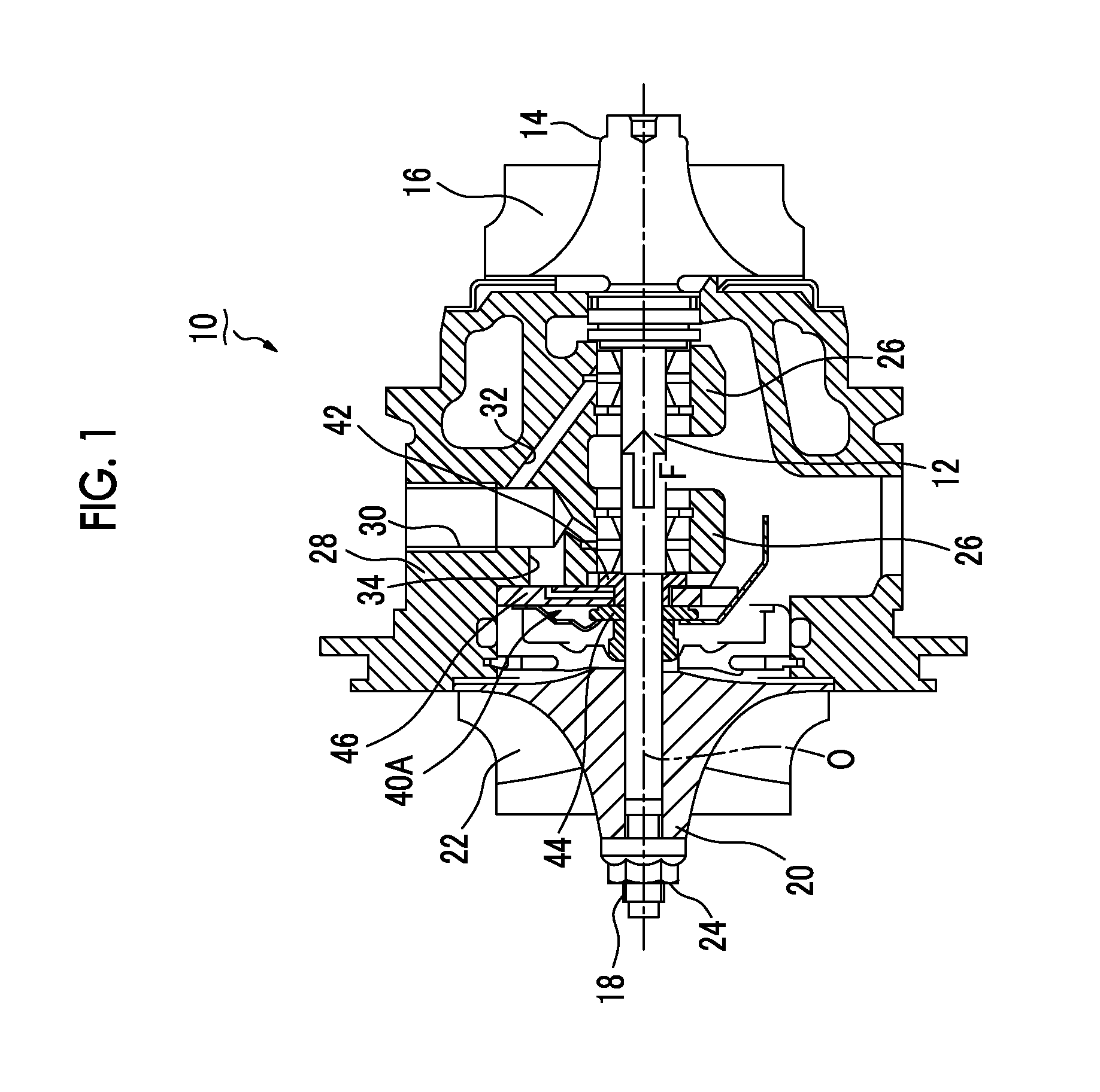
[0033]A first embodiment to which the invention is applied to an exhaust gas turbo supercharger will be described with reference to FIGS. 1 to 4. FIG. 1 is a cross-sectional view of an overall exhaust gas turbo supercharger 10 incorporating a thrust bearing device of the present embodiment. In addition, illustrations of a turbine housing and a compressor housing are omitted in FIG. 1. In FIG. 1, a rotary shaft 12 is arranged along a central axis O, and a turbine wheel 14 from which a plurality of turbine rotor blades 16 are provided to protrude in a radial direction is anchored to a shaft end of the rotary shaft 12. The other end of the rotary shaft 12 is provided with a threaded portion 18, a compressor wheel 20 is fitted and inserted from the threaded portion 18, and the compressor wheel 20 is fixed to the threaded portion 18 with a nut 24. The compressor wheel 20 has a plurality of compressor blades 22 provided to protrude in a radial direction therefrom.

[0034]The rotary shaft 12...

embodiment 2

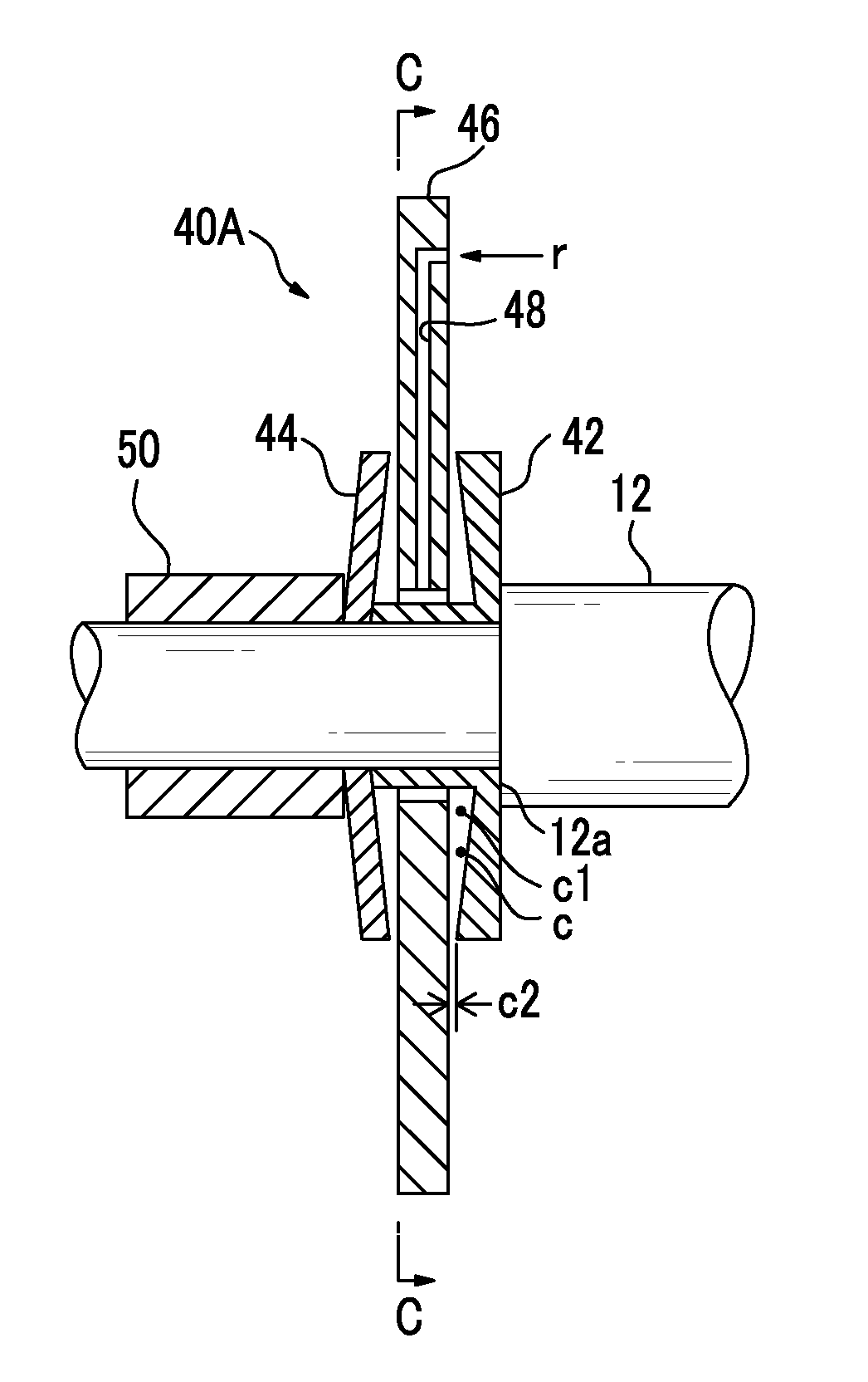
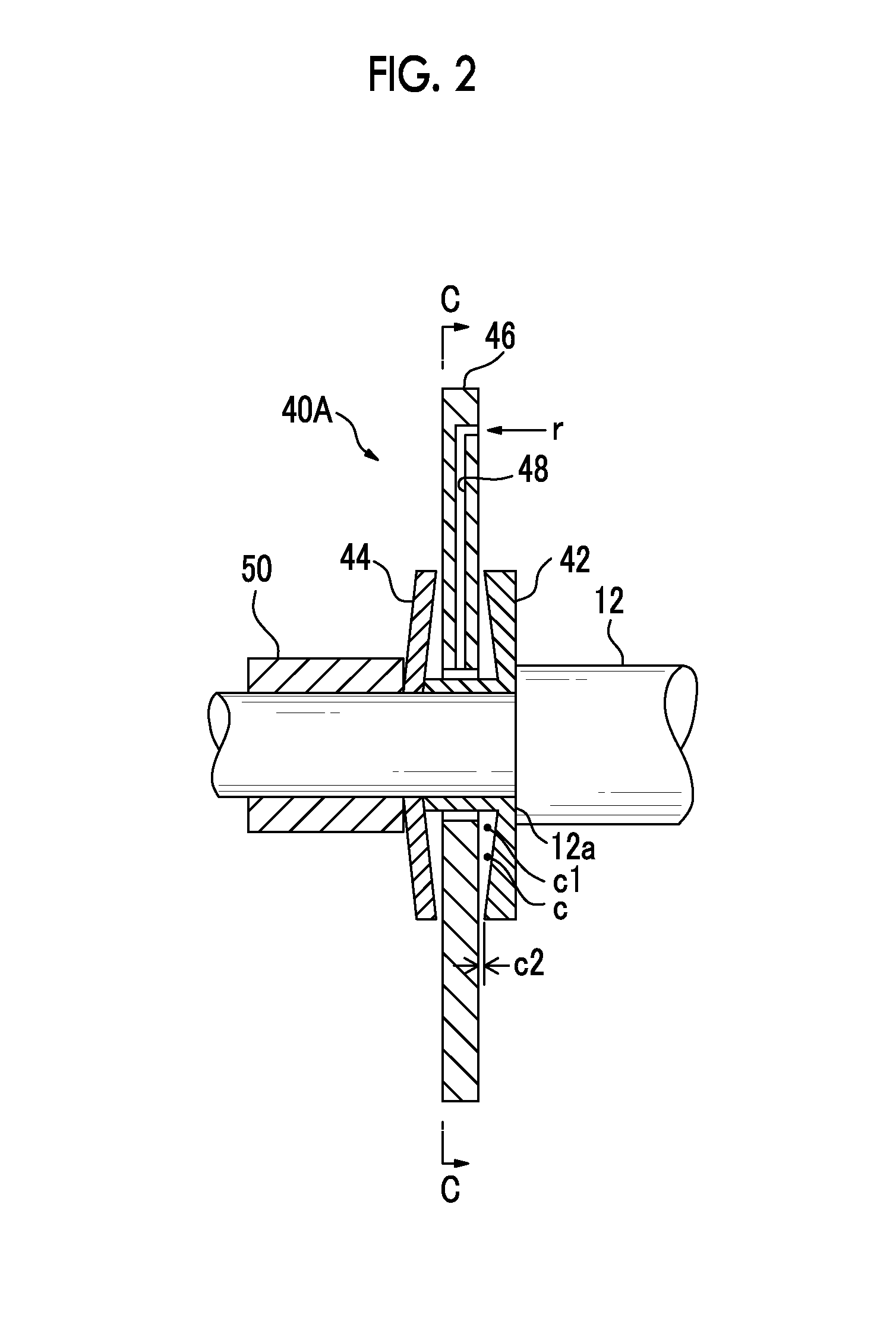
[0043]Next, a second embodiment to which the invention is applied to the exhaust gas turbo supercharger will be described with reference to FIG. 5. In FIG. 5, a thrust bearing device 40B of the present embodiment has the same configuration as that of the first embodiment except for the configuration to be described below. That is, in the thrust collars 42 and 44, land portions 62 and 64 that form planes parallel to the surfaces of the thrust bearing 46 are formed on outer peripheral sides of the inclined portions that have inclined surfaces with respect to outer peripheral surfaces (radial surfaces) of the thrust bearing 46. Each inclined portion has a minimum gap c2 with the thrust bearing 46 at an outer peripheral outlet, and the land portions 62 and 64 maintain the minimum gap c2 in the radial direction.

[0044]In the present embodiment, since the thrust collars 42 and 44 have land portions 62 and 64, oil film pressure can be made high to the maximum at the land portions 62 and 64....

embodiment 3

[0045]Next, a third embodiment of the invention will be described with reference to FIG. 6. In a thrust bearing device 40C of the present embodiment, the thrust bearing 46 and the thrust collars 42 and 44 do not have inclined surfaces unlike the first embodiment or the second embodiment, and are arranged in the direction perpendicular to the rotary shaft 12. Additionally, gap regions between the outer peripheral surfaces (radial surfaces) of the thrust bearing 46 and the radial sliding-contact surfaces of the thrust collars 42 and 44 form steps that are directed to the axis direction of the rotary shaft 12 at radial outer regions. In the present embodiment, the size of a gap c becomes basic region gap c1=stepped portion gap c3=outer peripheral end gap c2. That is, the thrust bearing 46 is formed to be thicker at an inner region than at an outer region, forms steps 72 and 74 on both outer peripheral surfaces at an outer peripheral middle position, and is formed to be narrow on an out...


PUM


Abstract

A thrust bearing device is constituted by a turbine-side thrust collar and a compressor-side thrust collar that are fixed to a rotary shaft; and a thrust bearing that is arranged between the thrust collars. The thrust bearing is provided with an oil passage that supplies lubricating oil r to sliding-contact surfaces formed between the thrust bearing and the thrust collars. The outsides of the thrust collars in a radial direction incline toward the thrust bearing side. A gap c between the sliding-contact surfaces is narrowed as the gap goes outward in the radial direction, and establishes a basic region gap (c1)>an outer peripheral end gap (c2). The lubricating oil outflow resistance of a radial outer region of the gap c becomes larger than that of a radial inner region. Therefore, the lubricating oil r can be kept from flowing out from a radial outer outlet.

Description

TECHNICAL FIELD[0001]The present invention relates to a thrust bearing device for a supercharger adapted to keep lubricating oil supplied to a thrust bearing from flowing out to an outer peripheral side due to a centrifugal force generated by rotation of a rotary shaft.BACKGROUND ART[0002]In superchargers, a thrust force is generated in a rotary shaft due to a pressure difference on a compressor side and a turbine side. Therefore, a thrust bearing is provided to stop the movement of the rotary shaft in a thrust direction. As the thrust bearing, bearings with simple structure, such as a taper-land type thrust bearing, are often used. However, when the rotating speed of the rotary shaft is fast, a centrifugal force acts on lubricating oil outward in the radial direction of the rotary shaft. Therefore, the outflow of the lubricating oil to an outer peripheral side increases.[0003]A thrust bearing is arranged to face the rotary shaft of a supercharger, and thrust collars that apply a th...

Claims


Application Information

Patent Timeline
Patent Type & Authority Applications(United States)
IPC IPC(8): F16C17/04
CPCF16C17/047F01D25/168F02B39/14F02C6/12F05D2220/40F16C33/1075F16C33/1085F16C2360/24
Inventor HAYASHI, NORIYUKISUZUKI, HIROSHI
Owner MITSUBISHI HEAVY IND LTD
Why Eureka
Try Eureka